• The rules for The Exchange can be found here. Please read and follow them. Stop using Paypal Friends & Family and follow our best practices to prevent getting ripped off or having a bad deal.

Grinder in a box! DIY grinder kit

Status
Not open for further replies.
Feedback: 3 / 0 / 0
Joined
Aug 8, 2004
Messages
227
Greetings all! A while ago, a grinder kit came on the market. Things happened, and it was no longer available. Then, Chris (aka blindhogg here) redrew a similar design. The cad files can be found at http://blindhogg.com/eerfgrinder.html

We talked a bit, made a few changes, and this is what came of it. I'll be offering this grinder kit for $250 plus shipping ($10.20 in the US via USPS flat rate box.) I can only make it to the post office to ship these on Fridays. I'll have everything boxed up and ready to ship each week. When ordering, please include which platen style you'd prefer (pictured below). I accept credit cards only at this point.

If you want to use a MAP arm it will not work with the current design of this kit. As the kit progresses, there may be a way to use them together.

Here is what is included:
entire_kit.jpg


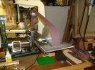
And choice of either platen style. The top one is the multi platen, it uses a small wheel at the top, a large wheel at the bottom and the platen itself inbetween. It can be rotated to use any portion. The bottom one is the standard platen. It's meant to have two smaller wheels with the platen itself inbetween. It can rotate to different angles.
platens.jpg


There is a little assembly, drilling, tapping, and countersinking a few holes. Wheels and a motor are not included. It is designed to use a motor with a 56c frame.

The tooling arm mount is 1 1/2 inches as is the work rest. All the pieces are laser cut from 1/2" steel. It assembles to a very sturdy grinder.

My information page for it is located at http://www.polarbearforge.com/grinder_kit.html. The page contains assembly instructions, a tool list, and a couple estimated pricing breakdowns depending on style of platen.

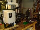
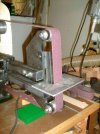
This grinder can be setup to use 72" belts. I setup one of mine with a 60" belt, and the rest will be 90". There's a lot of room for adjustment, it's all dependent on the length of the tooling arm.

I run 90" belts, so I make a mockup of a 72" belt to show the proportions of an assembled grinder.
grinder_72_mockup.jpg


I have some pictures of completed kits that I'll be adding to my website in the next few days.

I think that's most of the information. If there are any questions, please ask me. Email is the easiest, jamie at polarbearforge dot com. Thanks!

Jamie
 
:thumbup:I would like to thank Jamie and Chris for all of there hard work on the kit design. They were always willing to take time to answer questions, share there designs and always open to new Ideas. It was a pleasure working with them on this project and I look forward to working with them again.:D
 
I have been loosely following the development of this unit and am convinced I will have to have one at some point. I have a couple of questions, though.
First, what is the MAP arm and what would need to be done to make it work with this kit?
Second, this kit is designed to use KMG attatchments, correct? Will the KMG small wheel attatchment work on this machine?
Thanks for putting this together, it looks to be the best value going for a solid grinder chassis.
 
Thanks!

Justin, the MAP arm is a highly adjustable workrest made by Adammichael Knives. As of right now, I don't have a solution to make it work.

The tool arm mount is 1 1/2" square so that KMG accessories can be used with this as well. The small wheel attachment as well.

Jamie
 
With the flat platen how do you flat grind against it? The way it's set in your pic it looks more like a slack belt set up.
 
It is setup for a slack belt in the picture. The bolts above and below center are for attaching the phyiscal platen.

Jamie
 
I have been loosely following the development of this unit and am convinced I will have to have one at some point. I have a couple of questions, though.
First, what is the MAP arm and what would need to be done to make it work with this kit?
Second, this kit is designed to use KMG attatchments, correct? Will the KMG small wheel attatchment work on this machine?
Thanks for putting this together, it looks to be the best value going for a solid grinder chassis.

I am currently redesigning some of the components of this grinder to accommodate the MAP Arm. I planed on having these parts cut locally for my own use so I made changes to some of the parts to work with the MAP Arm and other changes to make the grinder look cooler (to me). This grinder is amazing the way it is but I just cant leave well enough alone.

If there is enough interest in making this grinder work with the MAP Arm, I think it can be accomplished with one additional part. Maybe it could be offered as an option to the kit.

I'll post pics tomorrow of my MAP Arm version of this grinder and if there is a demand for the optional MAP Arm piece, I can model it and get everyones feedback at that time.

You guys did a great job, everyone should be very proud of the hard work they did on this project

Michael
www.AdamMichaelKnives.com
 
Last edited:
So, going over the page on your site, it looks like besides the necessary parts listed for the standard platen kit, one would need to supply a tooling arm and a piece of angle iron for the platen itself?
I'm getting close to pulling the trigger on this, but I need to pin down prices and sources for all the bits and pieces first (minus the bolts which I probably have most of).
 
So, going over the page on your site, it looks like besides the necessary parts listed for the standard platen kit, one would need to supply a tooling arm and a piece of angle iron for the platen itself?

Yep. For my platens on my old grinders, I used angle iron as a support, and attached a hardened piece of A2 for the actual grinding surface. It's lasts longer. Here's one of my platens. It's for one of the new grinders, and has one of the previous versions of the standard platen. You can see the slots for adjusting the position of the platen, and the platen itself is a 5/8" piece of mild steel that will be replaced with A2 once I get it heat treated.

I'm in the process of building pedestals for my new grinders and will replace my current grinding bench. I'll add pictures to the website as I get them completed.

Brianml, here's a picture of the multi platen that shows it in it's different positions. There is not a physical platen attached in these pictures. You can see how it rotates to the different positions.

Jamie
 
Last edited:
Last edited:
Just a progress post for me. The kit pieces all fit well together. Mine is finished except for the motor and wheels and toolong arms. They should all be here this week. I will weld some areas after I check for alignment and belt tracking.
I have made a few changes. I ordered both platen types. For the multi platen I did the 1/2 x 13 helicoil inserts for the contact wheels and 3/8 x 16 helicoil inserts for the platen attachment. This will allow for full 360 degree rotation of the platen without the nuts hitting the tooling arm. On the flat platen, this is not as important as it does not rotate far enough for the nuts to hit. I am however adding the helicoils so that both platens are the same. The flat platen did not need the 3/8 helicoils as the holes were the correct size for a 3/8 tap.
I also took some 1/2" x .015" brass stock and made 2 bushings for the idle wheel arm where it attaches to the upright. This removes some of the slack where the 1/2" bolt passes thru. Probably not necessary, but I am anal that way!
Thanks to Jamie / Chris and others for the tips and putting this together.
 
I have a motor with a 56J frame, will this bolt up to this kit or would I need to drill new holes/slot the existing ones to make it fit?

Edit: I think I answered my own question after a bit of research.
 
Last edited:
I am 99% finished with my grinder. I misplaced one nut with the plastic insert and I have to order a graphite backing for the platen, but otherwise it is complete.

Specs are as follows.

Adjustable platen and a dedicated 8" wheel set up. Platen is made from angle iron and a piece of 1/2 steel. This is what I found at the scrap cutoff store.
2 HP motor 56c frame with feet. I found a motor in stainless rated for washdown. TEFC
1800 rpm ( I probably should of went with the 3600 rpm.)
220 v VFD single phase to three phase. Also Nema 4 case.
Tool rest.

I spent about a weekend and a half and a few evenings to put it together as well as about 47 trips to the hardware store.

I tried it out and it runs like a dream.

Thanks to Chris and Jamie for taking a bad situation to a winning one.

Eric
 

Attachments

  • grinder3sml1.JPG
    grinder3sml1.JPG
    70 KB · Views: 1,016
  • grinder4sml1.jpg
    grinder4sml1.jpg
    41.8 KB · Views: 1,177
  • grinder5sml1.JPG
    grinder5sml1.JPG
    79.3 KB · Views: 1,068
For the multi platen I did the 1/2 x 13 helicoil inserts for the contact wheels and 3/8 x 16 helicoil inserts for the platen attachment. This will allow for full 360 degree rotation of the platen without the nuts hitting the tooling arm.

That's a good solution. I'll look further into helicoils for this application. In my mind, I had envisioned a spacer between the multi platen and the tooling arm, but this seems more elegant. Thanks for sharing!

Jamie
 
I am 99% finished with my grinder. I misplaced one nut with the plastic insert and I have to order a graphite backing for the platen, but otherwise it is complete.

Wow! Looks good! It looks like it's already painted? Everybody is going to have theirs painted or powder coated before I do! :eek:

Jamie
 
Status
Not open for further replies.
Back
Top