Helve hammer design

Joined
Aug 6, 2007
Messages
5,060
So my idea is to build a small helve hammer similar in size to the Depew, 60 pound anvil from 2 3/4" round with a 2-4 pound head (20:1 anvil hammer ratio), metal arm, with the tire friction drive like a larger tire hammer. One of the main design goals is a powerhammer one person can lift into a pickup, but some of the other aims are small footprint, cheap and easy construction design, no need for special foundation, single phase 110 power requirements. Will aim for around 400BPM, will have pictures of the build. Here is a rough paint program design of the idea, the bit on the side is a top down view of the eccentric/crank with the pillow blocks on either side, offset will be 3" for a 6" stroke. Will incorporate the double crown round dies I made up for the Say Mak in the other thread, as well as some flat dies. To adjust for different stock thicknesses (like it needs it, top's it will work 1" which won't require much adjustment for thickness) the dies can be made shorter. Really the only thing I need to buy is the motor and 4 pillow blocks. Input and critique welcome.
 

Attachments

  • helve hammer design.JPG
    helve hammer design.JPG
    13.4 KB · Views: 255
Forgot to add in the picture, there will be a tying in cross member from the rear pivot supports columns to the anvil.
 
I am really looking forward to see this getting built.

the one suggestion I could offer, based on another design I saw, would be to modify the connection between the hammer arm and the isolating spring, to allow for the spring to be adjusted along the length of the hammer arm for fine tuning the hammer. I don't recall what design it was I saw the feature on, but assuming the hammer arm is 1"x1" square tubing, then the point where the isolation spring connects to would be a secon peice of 1x1, which is then clamped to the hammer arm and can be adjusted along the length of the hammer arm.

I've never built a power hammer, but the concept seems to alolow for additional flexibility in tuning a hammer that hasn't been built to exacting spec before and once the optimum location is determined, could possible be more solidly mounted, or left adjustable.
 
...you're going to lift he motor with the foot pedal ?

I'd change that somehow to reduce foot fatigue...fine control would disapear when i'm tired.

super duper long leverage and some spring assistance might do though...
 
I agree with kindyr, there should be some sort of tuning ability for the arm. Low frequency harmonics are a powerful force at 6 cycles/second. Besides the need for bracing, make sure the rear post is beefy. A lot of force may transfer to it. The motor can be suspended on a hinged plate so it hangs just clear of the tire. The foot pedal can pull/push it against the wheel. Some sort of cam is all that the end of the foot control arm needs. A skate board wheel, or similar wheel, would work fine for the cam roller ( to reduce the friction and make control very smooth). I can draw this up for you if you need to see what I am talking about.

Several of the plans for tire hammers use a leaf spring for the helve. This gives both flexible strength and deals with the vibrations.

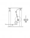
As far as being able to be picked up by one person......I don't know about that. There will need to be a certain amount of mass to the base as well as the unit itself. I would think that at a minimum ,it will end up weighing nearly 200 pounds. Some sort of sturdy wooden base will be needed to bolt it to as well. Also, the drive tire needs some mass to act as a flywheel. If the motor is 1750RPM, the 400BPM drive ratio for the motor-tire is about 4.5:1, so a 16" diameter tire will need to be driven by a 3.5" wheel on the motor shaft.

By keeping the hammer so small ( 2-4#) you may be able to get around some of these problems, but the unit will be pretty low power. Remember,the resulting power of a hammer blow is a function of the weight of the hammer and the distance it travels. A hand blow that drops 12-18" with a 3# hammer delivers 36-54 inch pounds of energy. A 3# hammer that rises and falls 4" delivers 12 inch pound. That is basically what power planishing hammers do. For doing decorative work on 18-20 gauge sheet metal this hammer will be great. For drawing out 1/2" steel, I don't think so.

I know you have seen them before, but take a look at the Rusty/Dusty plans and consider using some of those ideas in your light weight hammer build....or building a Dusty.

Final comment ( directed to all who are reading this as well as Sam):
In a power hammer mass is a lot of what makes it work. We all would like a 100 pound tool that does the work of a 1000 pound tool, but physics gets in the way of those plans. If anyone is considering building a home made power hammer, there are a lot of technical things you have to cover. When you start getting to 400BPM,things don't work as simple as a water driven 500 pound helve hammer delivering
2-3 BPM ( and weighing many tons).
Also, when things come apart ( and with power hammers they do) all that energy is transfered to the flying arms, bolts, and springs on a power hammer. It can easily be a lethal blow received from a mishaps while building and operating a power hammer.

FWIW, I don't think this project will do much at less than 10# hammer weight.
 
Stacy, You bring up EXCELLENT points thank you.

I think maybe you forget as per your comment on hammer size that speed also has something to do with the amount of force delivered. Force = Mass x Accellaration IIRC?

The tuning ability in the arm resides in the connecting rod, there will be a turnbuckle in the center of the connecting rod. Also the amount of spring extending from the pivot can be adjusted, as it clamps between the hammer arm and the pivot plate, the drawing does not show this in sufficient detail.

I have seen the Rusty/Dusty/Krusty hammers, my main build idea is to not build one of the standard schools of home build hammers, IE the Jerry Allen Rusty, the Clay Spencer Tire Hammer, The Ron Kinyon Air Hammer.

Gotta go to my Sis' for dinner, more to come.
 
the Jerry Allen Rusty, the Clay Spencer Tire Hammer, The Ron Kinyon Air Hammer.


Can

anyone post plans of these, or show me where they are?
 
There's no plans available from Ron Kinyon, thanks Chris for the link to Jerry Allen's Rusty, Clay Spencer tire hammer pictures can be found by searching Spare Tire Hammer on google, Clay also offers classes to build his hammers for 1200$ and you walk away with a running hammer.
 
Sam,
Here is some good helve hammer build info - http://www.fergusonsculpture.com/helve/helvearticle.html

Yes the formula is F=ma. The a( acceleration) is a= d/t*t (distance traveled divided by the time squared). The distance in your hammer is small and constant, the velocity is controlled by the speed of the hammer blows, and is a fixed factor once the hammer is tuned. I don't think your hammer design can survive 400 BPM, so lets use 200BPM as a rate.
For your `1.5kg (3#plus) hammer, traveling .075 meter ( 3"), in .3 second ( 200 BPM) the force would be 1.25 newtons per blow.
In contrast, a 3# hammer swung by hand over 20" in .3 second delivers about eight times that force .
 
Yeah but by your calculations, it will do 2.5 Newtons (because the swing will be 6" not 3") per .3 seconds, with using a .1% messup ratio, that's 7.5 Newtons per .9 second, and if a hand hammer can do 4 times that but you can't hit 3 times a second with a 3 pound hammer, so in reality only get 1 hit per second that means 30 Newtons per second IF you can keep up a full 100% blow rate with a 3 pound hammer continuously all day. Will it outhit a hand hammer blow for blow? NO. Will it outwork a hand hammer, effectively enough to make a difference? If the difference is you are exhausted by the end of the day and possibly injure yourself or you got 85% of the work done instead of 100% but are not exhausted then yes, if not then no. These are tuned the same way as an LG, you get it right when you hit the perfect harmonic resonance with the amount of spring with the rotation of the offset crank.

That's a good link!!!!!!

Stacy, I love your lines of thought, but also remember, this really is just for fun. It'll move metal for sure, but like I said if I need any real work I already have my Anyang or the big Say Mak at work, just like in the evolution of hammers through time the helves were phased out early on in the industrial revolution due to the effectiveness of the upright hammers and the advent of the dupont and dupont style linkage.

I have this same topic going on 4 different forums, getting lots of input and one main is the BPM, which I don't think will be so high. But to your question on structural integrity, there were wood armed helves regularly running in the 300-400BPM range with mortised and wedged on heads for years, not saying they were safe but just saying it was done in majority. I've learned my lesson about making things go faster than they should :D
 
Last edited:
Sam, if the idea is to be able to load it in a pickup, why not go with a bigger anvil and hammer and have the anvil attach in such a way as to be easily removed. I like the crank shaft design. As pointed out, the motor should near balance so it takes little effort to engage.
 
Jim, that's a good idea, unfortunately the steel I have is free (and i'm saving the 7" round for something else :D). Ordered the pillow blocks tonight~! Just need to get the tire and am all set!
 
Back
Top