Large Sebenza/Insingo FULL BACK SPACERS...

Joined
Feb 27, 2013
Messages
1,048
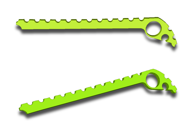
I've began working up what hopefully will result in a full back spacer for the CRK Large Sebenza and Insingo. There are a couple of issues right off the bat that make this more difficult than the back spacers for the Small Sebenza/Insingo... however I think these can be resolved with design tweaks.

Forum brother 91bravo has generously supplied one of his Large Insingos for me to disassemble and scan. The scans will allow me to be able to work the knife up in CAD and then CAM applications to arrive at machinable files.

The first hurdle I've encountered is the very tight tolerance of the Insingo blade to the lanyard hole. It turns out to be so close that my idea of machining my own stepped lanyard pin to solve the back spacer free rotation issue is not feasible. Even a small shouldered or stepped pin will have a strike issue. It also appears that the lanyard pin hole in the back spacer cannot even be full circumference for the same reason.

I'm still going to machine a carbon fiber lanyard pin however it will not be stepped or shouldered. If I can maintain a non-strike clearance with a straight lanyard pin it will require fixation into the back spacer with a dab of CA adhesive or epoxy.

We shall see... more as it happens...!

SLiC2vS.jpg

eiAwx6P.jpg
 
Why don't you have a .1875 hole rather than a hole to fit the backspacer in? Just a general observation as I have made similar ti backspacers for the Umnumzaan.
 
Why don't you have a .1875 hole rather than a hole to fit the backspacer in? Just a general observation as I have made similar ti backspacers for the Umnumzaan.

I'm not at all familiar with CRK knives with the exception of the short amount time I spent with the Small Sebenza and now the Large Insingo. The precision these knives exhibit told me that I didn't want to fool with change. I just wanted to add the back spacer and not affect the mechanical geometry. The stock round back spacer is a fixed dimension precision component. Eliminating that and using the carbon fiber back spacer just had the potential for introducing the slightest misalignment causing issues such as binding. Didn't want the headache.
 
I've got the scans completed and now I have the CAD files. I do this frequently enough and I have had at times great initial success and I've also had struggles with nailing the critical landmarks. This go around was spot on with the first attempt! Harmonious outcome...!!!

I then imported the CAD vectors into my CAM application and wrote some machining code for the first test. Below are a couple of pics of the test back spacer in coyote brown G10 scrap. The red arrow in the closeup points to the tight tolerance between the blade and lanyard hole. I'm still looking to machine my own straight pin which will get epoxied into the back spacer. I will probably need to kerf the pin to create sufficient blade clearance. Still thinking that one through...

t6tuvGp.jpg

YAfshX4.jpg
 
After thinking about this spacer a bit I know the carbon fiber is stiff enough so I can design the under spine to accommodate the blade belly. I wouldn't have to have a separate kerfing operation for clearance.

I'll need to look closely at this thin spine in the Micarta version. Won't know until I have one machined and can Jack Armstrong it a bit and see if they will be stiff and strong enough. May have to retain the thicker spine and kerf the Micarta version for blade closure clearance.

3Jqyymq.jpg

pUr7qoS.jpg


With that tweak in effect I can move onto the anti-rotation fixation pin. That's the last bit of imagineering I need to do on these. I could have a PROTOTYPE machined up in the next day or two...
 
OK... after struggling mightily with the uber tight clearance issue with the blade tip and the lanyard pin... I am slowly arriving at the conclusion that back spacers for a Large Sebenza Insingo 21 is iffy. I played for hours with the idea of a two part design... the back spacer and a straight lanyard pin which would need to be epoxied into the back spacer. This epoxied pin would provide stub posts that fit the lanyard holes thus preventing rotation of the full back spacer around the stock round back spacer.

The pin itself got too involved with the number of operations needed to arrive at nothing more than a short length of a small carbon fiber rod .355" long and .185" in diameter. I abandoned that idea.

The solving of problems typically come to me at some early morning point in twilight sleep and early this morning I formulated another approach that MAY solve the problem.

Instead of a two part approach I thought to machine the back spacer and the stub post as a single monolithic piece. I'm going to machine this up this weekend and see if it has merit.

I'm going to try machining a stub post on just one side as indexed double sided machining gets back into the 'too involved' issue where the time and cost to create an end product gets punitive.

Anyway... here are some quick CAD renders...

25XYw0r.jpg

nw5EyJC.jpg

The arrow points out where a small relief kerf may be necessary to get that blade clearance...
 
Last edited:
Machined the inclusive stub post back spacer design... and it works perfectly. I just need to tweak the post diameter ever so slightly for a perfect fit.

In the last pic below you can see that minimal clearance gap between the blade and spacer at full closure. The blade stop design on these knives is absolute... so I do not believe there would be a blade contacting the spacer issue... but I will put a clearance kerf in the back spacer at that stub post location to be absolutely certain.

brIEgok.jpg

xgxNQNN.jpg

Ti8BNuc.jpg

c0tdb1r.jpg
 
Just machined the 2nd monolithic stub post test spacer with the needed diameter tweak. It now fits perfectly!

Time to machine the first carbon fiber version...! Maybe I'll do that tomorrow after I watch the DVR'd F1 race...!
 
The first carbon fiber back spacer has been machined. It fits perfectly however when I flipped the vectors in my CAM application to accommodate positioning the profile on a small scrap of CF... that caused the stub post to be machined on the opposite side of the spacer. I'm going to flip it back so it indexes in the lanyard hole of the presentation scale and not the frame lock side.

I have ONE last issue to work out... and that's a blade clearancing kerf or slot right there at the location of the stub post. Haven't as yet come up with how to achieve that. A Dremel and a small cutting disc or even a small burr bit would be perfect but I do not happen to own one. You can see in the last photo that the blade does clear the spacer however the gap is minimal. Better to be safe... I'll come up with something...

fPySeeJ.jpg

iHNefug.jpg

FVjWslk.jpg

aT9ucgk.jpg

YB6Hfea.jpg
 
Last edited:
Installed the back spacer in 91bravo's Large Insingo for a fitment check. I have not come up with a way to kerf the slight swell at the stub post for blade clearancing... so I closed the blade with great slowness and care and checked the clearance with magnifiers. It fits perfectly and it does clear.

Here are a few photos... for some reason I can't get the light to make the carbon fiber checkerboard pop in the photos...

ceTLT36.jpg

9AUChHd.jpg

7Sa5PyY.jpg
 
I'm sitting here staring at my personal L21 insingo, Carbon Fiber knife. Given the clearance issue you are facing on the monolithic lanyard pin in the version you've made why isn't there an issue with the OEM version? I'm stumped.

I'm fascinated by your machining and the process you are going through.
 
Hmm... I'm not sure I'm the best one to answer that question. I do not know the ins and outs of CRK knives.

What I consider and observe to be minimal clearance of the Insingo blade to the lanyard hole is just my opinion. Not sure what CRK deems tight or minimal. I stated previously that their blade stop design is solid and positively stops the blade when closed... and I can't see an over travel issue where the tip might contact.

I can't know if maybe I'm being overly cautious. I just would not want to put these back spacers out there and have one damage a customer's blade.
 
^^ I get that, and your pictures with everything partially assembled clearly show it would be close (or even in contact). Anyway.... not a critique, more just musing out loud.
 
Just thinking out loud, the material for the spacer is a softer bendable product and the front of it is not screwed or thightened to the handle in any way but if your hand, pants pocket or anything thats snags on it by mistake wont it make it lift up/out and thereby break the front of the spacer?
 
Back
Top