- Joined
- Nov 6, 2002
- Messages
- 79
Reversing the 1x30 belt sander
Warning: LONG
Feel free to skip down to the rewiring section.
Disclaimer
The drawings, procedures and words shared here are for information only. Your actions are your responsibility - VERIFY and CHECK information out before proceeding, and don't attempt anything without the required skills. USE THIS INFORMATION AT YOUR OWN RISK! I reject any liability for any damages or injury caused to people or property from the use of this information or from any associated links. No claims are expressed or implied as to the safety, usefulness, or accuracy of this information.
Background
I recently picked up a cheap 1x30 belt sander at Harbor Freight (item 2485-1VGA) for $30.
When I got it home I took it apart to see how it was built. I then decided to see if I could reverse the belt direction to improve its function as a knife sharpener.
Since the belt is driven directly by the motor the motor's direction of rotation must be reversed to change the direction the belt travels.
The motor proved to be a common single phase induction motor with a capacitor mounted its control box.
The Goal
Electrically reversing the sander's motor.
Theory
All single phase motors induction motors need some mechanism to get the motor's rotation started.
The most common method is to build the motor with two separate windings; a start winding and a run winding. A capacitor is typically used to shift the phase supplied to the start winding and thus start the motor.
The start winding usually has a higher resistance since it is wound from smaller wire.
The motor can be reversed by reversing the connections of either the start or run winding.
For full details see http://www.lmphotonics.com/single_phase_m.htm
Tools and Supplies
multimeter
dykes
wire strippers
knife
hammer
#2 and #3 Phillips screwdrivers
3 mm allen wrench
dpdt toggle switch (I used a Gardner Bender GSW-16)
drill and bits
18 awg, 600V, 105 degree primary wire
crimp connectors as needed
crimper
liquid electrical tape
1/8" heat shrink
zip ties
sharpy
Practical Application
After I opened up the motor's control box I found four motor leads: white, blue, black1 and black2. The white and black1 where connected to the power switch. Black2 and the blue where wire nutted to the capacitor leads.
At this point I thought I was home free; just swap two of the motor leads to reverse the motor's rotation.
So I label all the leads and get out the multimeter. The first thing was to measure the resistance between each lead to determine which one corresponded to which winding and to deduce the motor's exact type.
After some testing I recorded the results:
lead pair ohms
black1-black2 0.4
black1-white 9.2
black1-blue 26.0
black2-white 9.2
black2-blue 26.0
white-blue 17.1
Ok now I had a problem. Since black1 and black2 where shown to be internally connected by their low resistance I really had only three motor leads (black, white and blue).
My revised test data became:
lead pair ohms
black-white 9.2
black-blue 26.0
white-blue 17.1
Now it was time for some head scratching I either had to figure out what was going on inside the motor or just give up the project.
I don't give up easily.
After extensive research (Google) I found this site
http://www.homemetalshopclub.org/news/sep01/sep01.html (scroll down a bit) where the author talks about rewiring his imported carbide bit grinder. His motor is set up differently from mine but he mentions that due to OSHA regulation these motors have been made with one end of both the start and the run windings connected internally and brought out as a single lead. He claims that this is done to prevent the user from rewiring the tool to run in the reverse direction (thus preventing injuries). He get around this by swapping the capacitor with an inductor (an inductor provide a phase shift opposite to that provided by a capacitor).
Using this new information I reconsidered my test results and concluded that I had the expected two windings. Since 9.2 plus 17.1 is approximately equal to 26.0 I had one 9.2 ohm winding between the black-white pair, one 17.1 ohm winding between the white-blue pair and the both the windings in series between the black-blue pair.
The higher resistance (17.1 ohm) winding was taken to be the start winding.
Lead connections:
black -> one end of the run winding
blue -> one end of the start winding
white -> the other ends of both the start and run windings
Now to reverse the motor I either had to get use the inductor
technique or open the motor and separately bring out the ends of the winding originally connected to the white lead.
I chose to open the motor case.
Rewiring
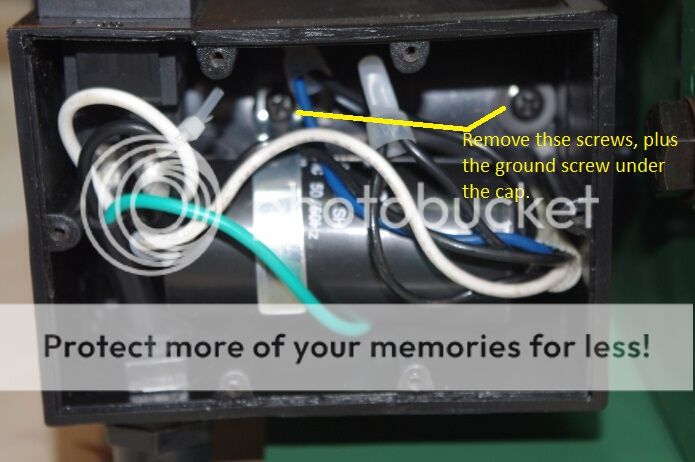
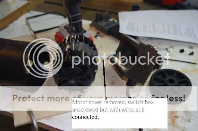
I first removed the motor from the grinder and then removed the plastic control box, the plastic shroud and cooling fan.
I then removed the bolts holding the motor's die cast end together and tapped the end caps off the stator laminations.
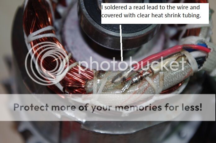
The motor's leads proved to be welded to the ends of the windings. This connection was protected by a fiber tube. I carefully exposed the white leads connection and cut off the end of the start winding.
I reconnected this end to a new red lead and insulated the new connection with heat shrink and liquid tape.
New lead connections:
black -> one end of the run winding
blue -> one end of the start winding
white -> the other end of the run winding
red -> the other end of the start winding
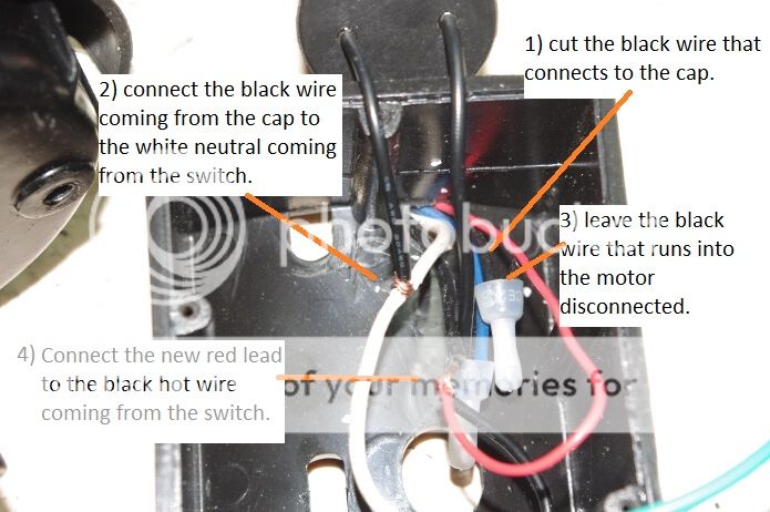
I then reassembled the motor, added a dpdt switch and wired is as
follows:
forward rotation
black -> hot
white -> neutral
blue -> capacitor -> hot
red -> neutral
reverse rotation
black -> hot
white -> neutral
blue -> capacitor -> neutral
red -> hot
Safety considerations:
The belt the grinder ships with is directional and will break if run in the wrong direction. Toss it and buy some quality reversible belts.
Always use care when grinding.
Warning: LONG
Feel free to skip down to the rewiring section.
Disclaimer
The drawings, procedures and words shared here are for information only. Your actions are your responsibility - VERIFY and CHECK information out before proceeding, and don't attempt anything without the required skills. USE THIS INFORMATION AT YOUR OWN RISK! I reject any liability for any damages or injury caused to people or property from the use of this information or from any associated links. No claims are expressed or implied as to the safety, usefulness, or accuracy of this information.
Background
I recently picked up a cheap 1x30 belt sander at Harbor Freight (item 2485-1VGA) for $30.
When I got it home I took it apart to see how it was built. I then decided to see if I could reverse the belt direction to improve its function as a knife sharpener.
Since the belt is driven directly by the motor the motor's direction of rotation must be reversed to change the direction the belt travels.
The motor proved to be a common single phase induction motor with a capacitor mounted its control box.
The Goal
Electrically reversing the sander's motor.
Theory
All single phase motors induction motors need some mechanism to get the motor's rotation started.
The most common method is to build the motor with two separate windings; a start winding and a run winding. A capacitor is typically used to shift the phase supplied to the start winding and thus start the motor.
The start winding usually has a higher resistance since it is wound from smaller wire.
The motor can be reversed by reversing the connections of either the start or run winding.
For full details see http://www.lmphotonics.com/single_phase_m.htm
Tools and Supplies
multimeter
dykes
wire strippers
knife
hammer
#2 and #3 Phillips screwdrivers
3 mm allen wrench
dpdt toggle switch (I used a Gardner Bender GSW-16)
drill and bits
18 awg, 600V, 105 degree primary wire
crimp connectors as needed
crimper
liquid electrical tape
1/8" heat shrink
zip ties
sharpy
Practical Application
After I opened up the motor's control box I found four motor leads: white, blue, black1 and black2. The white and black1 where connected to the power switch. Black2 and the blue where wire nutted to the capacitor leads.
At this point I thought I was home free; just swap two of the motor leads to reverse the motor's rotation.
So I label all the leads and get out the multimeter. The first thing was to measure the resistance between each lead to determine which one corresponded to which winding and to deduce the motor's exact type.
After some testing I recorded the results:
lead pair ohms
black1-black2 0.4
black1-white 9.2
black1-blue 26.0
black2-white 9.2
black2-blue 26.0
white-blue 17.1
Ok now I had a problem. Since black1 and black2 where shown to be internally connected by their low resistance I really had only three motor leads (black, white and blue).
My revised test data became:
lead pair ohms
black-white 9.2
black-blue 26.0
white-blue 17.1
Now it was time for some head scratching I either had to figure out what was going on inside the motor or just give up the project.
I don't give up easily.
After extensive research (Google) I found this site
http://www.homemetalshopclub.org/news/sep01/sep01.html (scroll down a bit) where the author talks about rewiring his imported carbide bit grinder. His motor is set up differently from mine but he mentions that due to OSHA regulation these motors have been made with one end of both the start and the run windings connected internally and brought out as a single lead. He claims that this is done to prevent the user from rewiring the tool to run in the reverse direction (thus preventing injuries). He get around this by swapping the capacitor with an inductor (an inductor provide a phase shift opposite to that provided by a capacitor).
Using this new information I reconsidered my test results and concluded that I had the expected two windings. Since 9.2 plus 17.1 is approximately equal to 26.0 I had one 9.2 ohm winding between the black-white pair, one 17.1 ohm winding between the white-blue pair and the both the windings in series between the black-blue pair.
The higher resistance (17.1 ohm) winding was taken to be the start winding.
Lead connections:
black -> one end of the run winding
blue -> one end of the start winding
white -> the other ends of both the start and run windings
Now to reverse the motor I either had to get use the inductor
technique or open the motor and separately bring out the ends of the winding originally connected to the white lead.
I chose to open the motor case.
Rewiring
I first removed the motor from the grinder and then removed the plastic control box, the plastic shroud and cooling fan.
I then removed the bolts holding the motor's die cast end together and tapped the end caps off the stator laminations.
The motor's leads proved to be welded to the ends of the windings. This connection was protected by a fiber tube. I carefully exposed the white leads connection and cut off the end of the start winding.
I reconnected this end to a new red lead and insulated the new connection with heat shrink and liquid tape.
New lead connections:
black -> one end of the run winding
blue -> one end of the start winding
white -> the other end of the run winding
red -> the other end of the start winding
I then reassembled the motor, added a dpdt switch and wired is as
follows:
forward rotation
black -> hot
white -> neutral
blue -> capacitor -> hot
red -> neutral
reverse rotation
black -> hot
white -> neutral
blue -> capacitor -> neutral
red -> hot
Safety considerations:
The belt the grinder ships with is directional and will break if run in the wrong direction. Toss it and buy some quality reversible belts.
Always use care when grinding.
")