The "Ask Nathan a question" thread

Hey Nathan wanted to ask about BTE of HDMC.
on Behemother BTE is .040" as far as I remember, what about HDMC?
thickness at ricasso is same on both Behemother and HDMC - .275" so BTE is same also or?
HDMC is indestructible knife as far as I know. I've seen you cutting bolts with it.
what about Behemother? will it perform same in same scenario or?
in terms of toughness, geometry plays huge role as far as I know, so BTE means a lot when "cutting bolts" :D

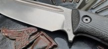
The HDMC is a more obtuse primary bevel geometry and thicker behind the edge than the Behemother. However both will cut a bolt. The Behemother is a high performance cutting tool the HDMC is an indestructible WMD
 
Another Not Nathan! When I order 3V steel, it either comes precision ground or not.
If it is, then it is already a smooth shiny finish. If it isn't, then it is oversized and grey, but not a brute-de-forge texture that you want.
(also, since it is oversized, without machining it wouldn't match the desired design specs)
 
I don't think the machining process leaves much 'bark', unlike hand/hammer forged blades.

Another Not Nathan! When I order 3V steel, it either comes precision ground or not.
If it is, then it is already a smooth shiny finish. If it isn't, then it is oversized and grey, but not a brute-de-forge texture that you want.
(also, since it is oversized, without machining it wouldn't match the desired design specs)

Thanks for the reply(s) Worth a shot. Was hoping to be able to have something like on the HDFK D2 in D3V or AEB-L w/ same rough finish. Admittedly not knowing the effect of what process/machining and or different material(s) there may be.

20210414_181133.jpg
 
Thanks for the reply(s) Worth a shot. Was hoping to be able to have something like on the HDFK D2 in D3V or AEB-L w/ same rough finish. Admittedly not knowing the effect of what process/machining and or different material(s) there may be.

View attachment 1549272
Ah, I see, maybe Nathan has a process for that finish, let's hope he chimes in...
 
Thanks for the reply(s) Worth a shot. Was hoping to be able to have something like on the HDFK D2 in D3V or AEB-L w/ same rough finish. Admittedly not knowing the effect of what process/machining and or different material(s) there may be.

View attachment 1549272

The bark on those D2 models was awesome. I believe I've seen Nathan post in the past that it just doesn't come out that good with 3V. Man it'd be awesome if it did, love that look!
 
Hi Nathan,
A knife CAD question. Presumably you have some sort of inter-part link or associativity between blade model and scale model so that profiles match and changes are more easily implemented? What do you find makes the most convenient master part, the blade profile, from which you derive the scale, or the other way around? I have tired three different hierarchies and the one that seems to function best for editing and adjusting the handle shape is the least tidy.

Thanks.

Chris

My blade model also works as a master model with the handle modeled as surfaces. There is an assembly where those surfaces get pulled into a sub model and made into a solid. This works pretty well because the complex surfaces of a handle model ends up being done with advanced surfacing anyway, so I just leave them as surfaces and solidify them in the sub models. There's also associativity to the toolpaths. This allows me to machine prototypes and adjust the handle design in an iterative fashion before going into production. They always need tweaks.
 
Thank you Nathan.

Your answer generated a bit of a "Huh?" moment, I will need to go away and digest.

I have always turned my surfaces into a solid in my handle model, which is associative with the tool paths too. I started with a blade part and a handle part, both placed in a higher level blade/handle assembly and used an association from the outline of the blade and tang to the handle part. Thing I found was that sometimes the surfaces didn't like some aspect of the tang shape, or I would want to adjust the handle profile, and it was a bit of a pain switching parts, changing, switching back and running an update/refresh to make the change.

The untidy method I mentioned had the blade profile sketched out in the handle part and then read across into a blade only part. All profile changes then made in the handle part, which I find the more fiddly and most likely to need many tweaks.

I will have a look at your method!
 
Actually, another CAD question has come to mind. Base coordinate system.

Do you use one associated with a feature which then remains constant through the iterative process, or do you just have one off in space and all curves and features are free to move?

I was being consistent with my base coordinate coinciding with the front handle screw, but I came to do some mix and match with an earlier design where I had used the blade tip as the origin and it has been a pain getting the two models to line up correctly. Not helped that the older model had a bolt hole that was in a different place relative to handle depth and leading edge.

My industrial experience hammered home to have the base coordinates associated with a real physical feature, ideally the one that would be used as a drawing/machining reference or datum. Not so difficult when everything is circular bores and flat flanges :D:rolleyes: rather less straight forward when so much is splines and lofted surfaces.
 
I like having all of the modeling for the scales performed in the blade model. The scales files are only a few features, all the real surfacing is done in the blade file and then hidden. I have to go to the assembly file and regenerate to get the scales current before cutting them if I've made any changes. Using the part file as a master model is not best practices in an industrial setting but I own the company and I do what I want.

Some people would recommend a skeleton model or to do it as you're doing it. But at a certain point some of the "best practices" become moot because their purpose is to allow easy changes to the design by anyone, but complex surfacing generally shouldn't be casually changed and should not be edited by just anyone. A good example of this in practice is complex and stylized molded plastic parts. You don't edit that geometry once it's finalized unless you're re-using the data on a new project. And most people shouldn't attempt to edit that kind of geometry because they'll create flaws and wrinkles in complex surfaces because they don't have the skillset to recognize and correct problems. If they want to change something they can cut or add, but they shouldn't change existing features in the model tree. BECAUSE THERE IS A GODDAMN MOLD ALREADY MADE THAT IS MOLDING PARTS. And the last thing you want to do is accidently change some geometry somewhere and now your live model doesn't reflect manufactured product. Any change is going to be a tool change and that change should be done in the model the same way it's going to be done in the physical mold. So, as a rule of thumb, if there is any kind of complex surfacing, those best practices (which are intended for the 95% of people who don't do real surface modeling) can be thrown out the window. IMO. So I like treating a master part as a master model and using it in place of a skeleton for complex geometry.

As far as datum planes and coordinate systems I often use the default and put it at the blade-handle transition. As long as you're symmetric across the plane of symmetry of the knife it really doesn't matter and my only reason for doing this is because I start with physical models and bring them into CAD once they're close. I create a line that represents my over all length and put the blade length on one side and the handle on the other. It's approximate. Then I reference this line as I start sketching and scanning to get my design into CAD, creating reference geometry as I go for various measurements.
 
Back
Top