Review WIP: Full Featured 2x72 for under $1500?!? Housemade Gen 4 Revolution Kit Build

Bühlmann

North Lake Forge
Knifemaker / Craftsman / Service Provider
Joined
Jan 6, 2022
Messages
475
This is the path I chose to take, and I think there are enough new guys like me out there that might benefit from knowing that there is another high quality, made in USA option out there that doesn't require selling a kidney to have. I'm not sponsored or affiliated by anyone in anyway, and I purchased everything you'll see with my own money. I'm just a guy with an interest and now a habit, and since I can't contribute to this site with gorgeous knives yet, I want to with this experience. I'm not going to go through all of the steps or instructions, because it's all available for anyone that buys the kit, but rather an extended summary to show a bit of me fabbing up my own and sharing the process and features that convinced me to try this out instead of buying a turnkey grinder. To date I've never sold a knife & I've never done a WIP, so be gentle.

The tooling required to build it is likely things you already have, and if you don't you will use it beyond this grinder build, so it is all good money spent. The welding may be a dealbreaker for some but it's all easy stitching, and if you have been wanting a welder this is a golden opportunity to pull the trigger on that, too! You can have a welder + 2x72 grinder for under 2K. Not too shabby.

Brian Housewert is the creator of the plans, cut kit, and outstanding YouTube video instructional series for this grinder. Since I can't link anything, you will have to search stuff out, but when you find his site you will find access to everything related to the build, and many more resources. I am very impressed with Brian's operation, and the interactions I've had with him are genuine and professional. This is his baby, and it shows in all of the work he has done to make this kit affordable and easy to fab up.

Enough with the intro. Screw it, let's do it!
 
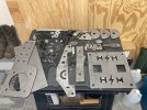
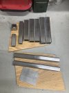
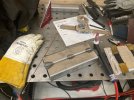
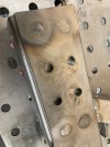
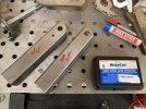
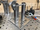
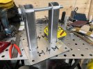
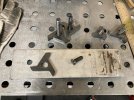
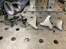
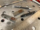
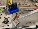
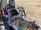
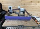
Here's the parts. Laser cut parts & fasteners in the first pic, tube set in the second.


IMG_0259.jpg

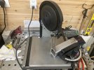
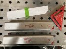
The tubes were soaked in vinegar for 48 hrs to remove mill scale then softened edges and buffed with a surface conditioning belt on my little Norse 2x42 that this will be replacing.

IMG_0260.jpg

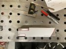
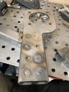
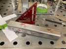
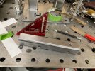
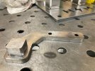
The squarish flat piece is some extra plate that I am planning on using to modify the platen D-plate. More on that later.
 
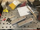
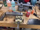
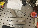
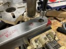
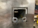
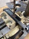
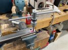
Starting with the receiver tubes, the holes were drilled with my little Shop Fox 12" benchtop drill press and then tapped for the tooling arm stop knobs. I am continually reminded that this size drill press is a compromise, and one that I think I will remedy with a mini mill in the future.

IMG_0261.jpg

IMG_0262.jpg

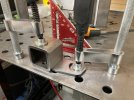
Keep your weld criticisms to yourself..... 😎

IMG_0263.jpg
 
If only I knew how to weld 😁 thanks for pics! Love seeing it come together
 
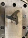
Cut out the tracking pillar last night. 1:1 templates are included in the plan package, which is pretty cool. Makes it mostly idiot proof, but I intend to put that to the test!

B3471F8B-B9EE-4242-95C6-E695F08F6CC2.jpeg


Realized by changing my portaband blade just how dull the original blade was. New blade cut much faster & smoother. This could easily be accomplished with a grinder/cutoff wheel combo too, if you don't have a bandsaw.


F6ED8A6F-F90B-4801-BA93-DDBFED088986.jpeg


Ready for fit up.

621BC089-91FC-4E44-84B1-F6849A96A2A5.jpeg
 
Last edited:
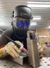
I really enjoy welding, which is one of the reasons I chose this route. I’m self taught on TIG, and honestly carbon steel more difficult for me than both stainless & aluminum. That’s the exact opposite of most, so I guess I’m weird. Anyways, here’s some progress shots as I’m waiting for it to cool.

4E66B8C0-71A9-4558-A1D2-0C435ACD651D.jpeg

4896D34A-3ACD-4766-913F-0E0B2E9725D3.jpeg


CB166353-F1AA-4A7B-809F-18D590A7EE6D.jpeg

337CC2BF-7A6F-452B-9B90-257EDA916CA6.jpeg
 
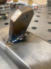
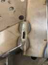
Time for the motor mounting plate. This is held on by filling plug welds to the receiver tubes. This is where TIG is difficult. With a MIG gun I could just basically shoot wire into the hole and fill ‘er up. Getting the tungsten and torch cup in there isn’t possible, so I extended the tungsten way out beyond normal to get good arc. It’s less than ideal, and a real bitch to not arc to the sidewall or touch my filler to the tip. I don’t think these plugs will be x-ray quality welds, but there is solid fusion and much surface area, so it’ll do. Just as good or better than flux core, I’m sure.

CE3A176B-BD78-4A31-A6A5-4984E3DEF68D.jpeg

65EDED39-ACAB-4055-869C-B958EF937B8F.jpeg

MIG is definitely the preferred process here. Pouring more heat into this frame than I’d like, so have to take it slow. Might have to add a MIG machine to the fleet…. 😂
 
Last edited:
And I ran out of argon. First 80lb bottle through that welder. So I’ll finish those plugs later. Let’s move on to the risers.

I deviated from the instructions a little here for a couple of reasons:

1. My drill press is small, and I couldn’t work out a practical way to drill these hinge pin holes in one operation with the table height, height of my mill vise, and short stroke of of the press.

2. I think a 3/4” twist drill makes a crappy hole. This is especially true if your setup isn't rock solid like with a mill.

I was able to manage issue #1 with a small pilot drill bit, but the length of the chucked bit is ultimately the limiting factor. So I decided to use Brian’s instructions for drilling a 1/8” pilot through both walls in one operation. Then used a Hougen RotaCut carbide hole cutter to complete each hole using the pilot hole as the cutter guide on each side. This two-step alternative worked beautifully, allowing my less-than-ideal drill press to tackle this task with precision.

8B587C35-C5AF-414D-81CD-E8753FEDFD7E.jpeg

EEEE70A4-2926-4CB5-BAB3-E5DA1369355D.jpeg

019434EE-50CA-4C45-BCA6-0DAFCD362D40.jpeg


37555B2A-5CF2-4AA5-BBC6-B4F16B23DA21.jpeg
 
And I ran out of argon. First 80lb bottle through that welder. So I’ll finish those plugs later. Let’s move on to the risers.

I deviated from the instructions a little here for a couple of reasons:

1. My drill press is small, and I couldn’t work out a practical way to drill these hinge pin holes in one operation with the table height, height of my mill vise, and short stroke of of the press.

2. I think a 3/4” twist drill makes a crappy hole. This is especially true if your setup isn't rock solid like with a mill.

I was able to manage issue #1 with a small pilot drill bit, but the length of the chucked bit is ultimately the limiting factor. So I decided to use Brian’s instructions for drilling a 1/8” pilot through both walls in one operation. Then used a Hougen RotaCut carbide hole cutter to complete each hole using the pilot hole as the cutter guide on each side. This two-step alternative worked beautifully, allowing my less-than-ideal drill press to tackle this task with precision.

View attachment 1906618

View attachment 1906629

View attachment 1906621


View attachment 1906624
Looks great!

I think you have the base plate upside down.
 
Got a new 80lb bottle of argon and back to work. Today I finished the plug welds on the motor mounting plate, got the tracking bar drilled & threaded, the pillars tacked, and the hinges aligned and tacked. Also got to do a little tuning to get the vertical/horizontal planes perfect.IMG_0307.jpg

IMG_0308.jpg

IMG_0306[2868].jpg

So I re-learned a lesson I first learned long ago. See my short sleeves? Yeah, well the insides of my elbows and biceps have a nice "sun" burn thanks to my failure to respect the flash. Ouch. Dammit.

IMG_0311.jpg

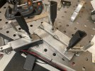
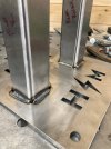
Here's the pillars squared & plumbed. I also deviated from the instructions a bit here, too. I placed a few washers under the pillars before lining them up and tacking. The reason for this is to ensure that any lack of flatness on the baseplate won't allow the pillars to sit below the bottom surface, creating a high center situation. My baseplate is flat, but this is just a little insurance and peace of mind on my part. The washers recess the pillars about 0.063".

IMG_0312.jpg

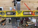
Digital protractor zeroed on the baseplate. Perfectly parallel at top of receiver.

IMG_0313.jpg

I was off 0.9

IMG_0314.jpg

I was 0.9 degrees off on my horizontal plane. Easy fix. Just buffed off a tiny amount off the top of the pillars where the receiver rests in the horizontal position to allow the extra range of motion. Took it slow, disassembling, removing just a few thousandths at a time, reassembling, and repeat until I was dead nuts at 90 degrees.

Now with all of the critical fab points complete, I'll go back and finish my welds out where I had only tacks.
 
Last edited:
This is great! Keep posting. I have been looking at this grinder, and this is giving me a much better idea of what making it would require.
 
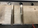
I forgot to mention that I got into a little bind with tapping the through holes in the tracking bar. I drilled the 5/16" through holes with a RotaCut bit just like I did with the large pillar holes, but when it came to tap the holes I realized that my tap had a shaft diameter that is the same as the O.D. of the cutting teeth, which meant that the tap was not going to go through the threads it just cut to continue cutting the opposite-side hole. That's important, because if your threads aren't "continuous", there's better than a good chance they won't sync up and your threaded fastener will bind up as it tries to engage in the second hole. Hope that makes sense.

Either way, I was lucky enough to have a second 3/8-16 TPI tap that I was able to modify by grinding the shaft down to slightly less than the ID of the cutting teeth of the tap. This allows the tap to continue to engage the opposite hole before the cutting teeth are out of the near-side (now threaded) hole, resulting in continuously synched threads. Mod'd tap on left:

IMG_0324.jpg
 
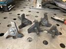
Knob day.....which is remarkably similar to motor mount plug welding day. I remember Brian mentioning in a podcast about the hex bolts being unique to source because they are threaded all the way to the head, instead of having a shoulder as most hardware store bolts do. That's a feature that allows the knob bolts to utilize the entire length of the bolt for adjustment. So, I decided to align the bottom of the hex head to the bottom of the knob to take full advantage of the threaded length. It'd be easier to just set the bolt on it's hex head and put the knob on and weld, but you'll lose 2-3 thread revolutions that way, and with my luck I'll need those 2-3 threads some day. So I did it this way. Again, a MIG machine would make much quicker work of this task.

IMG_0317.jpg

IMG_0319.jpg

I took a bit of aluminum plate I had and drilled a 1/2" hole in it to drop the hex bolts into and place the knob over, aligning the bottom surfaces. The aluminum also ensures that my fasteners don't inadvertently get welded to my welding table.

IMG_0321.jpg

Ground flat and ready to prep for finish. I'll probably break the edges more, and blunt the tips a bit.

IMG_0323.jpg
 
Last edited:
I forgot to mention that I got into a little bind with tapping the through holes in the tracking bar. I drilled the 5/16" through holes with a RotaCut bit just like I did with the large pillar holes, but when it came to tap the holes I realized that my tap had a shaft diameter that is the same as the O.D. of the cutting teeth, which meant that the tap was not going to go through the threads it just cut to continue cutting the opposite-side hole. That's important, because if your threads aren't "continuous", there's better than a good chance they won't sync up and your threaded fastener will bind up as it tries to engage in the second hole. Hope that makes sense.

Either way, I was lucky enough to have a second 3/8-16 TPI tap that I was able to modify by grinding the shaft down to slightly less than the ID of the cutting teeth of the tap. This allows the tap to continue to engage the opposite hole before the cutting teeth are out of the near-side (now threaded) hole, resulting in continuously synched threads. Mod'd tap on left:

View attachment 1909086
If you get a spiral point "gun" tap, you won't have to do that
 
Time to finish out the welds. Front & rear risers and the hinges get welded up.

IMG_0338.jpg


IMG_0341.jpg

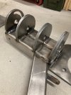
With those pieces fleshed out, I moved on to mounting the tracking bar and fabbing up the hinged tracking mechanism. The hinge is drilled all the way through, which called for some creativity on my part with my mill vice, a couple 1-2-3 blocks, and a two-part approach to drilling the .250" hinge hole due to my short little drill press. Again, less than ideal but a little redneck engineering with a sprinkling of select cuss words and I was able to persevere. It's a pretty critical operation that has a direct impact on the functionality and precision of the tracking mechanism.

IMG_0344.jpg

IMG_0345.jpg

IMG_0346.jpg

Tracking mechanism assembled and mounted with an Ameribrade 4" crowned tracking wheel.

IMG_0347.jpg

IMG_0348.jpg

The top of the hinge is able to rotate about 30 degrees or so forward and aft. The jackscrew adjustment pushes on the end of the tracking wheel mounting bolt to allow the hinge to swivel left & right. Pretty slick setup.

After that I assembled the D-plate and flat platen components. There was a few simple welds to make on the support legs to the flat platen backing plate, and a couple of holes drilled & tapped into the tool arm. I have ceramic glass platen liner on my 2x42 grinder and think it's a no-brainer to fit one to this one, too. I chose to use a rubber coated 2" wheel from Ameribrade for the top of the platen and a standard aluminum 2" wheel for the bottom. This way I can get the utility of a 2" contact wheel on the flat platen arm, which is a nice added feature, and on of the benefits of being able to spec out all of the parts for this build. The aluminum wheel is temporary, but more on that later. This operation makes it really take shape and look like a grinder!

IMG_0342.jpg
 
Last edited:
With that done, it was time weld up the handle assembly. Easy enough, just fit a piece of square stock for a plug and weld up. I ground it flat to look nice, and will tack it to the tracking bar once I mount handle material to it, just like knife scales.

I have a little complaint on the handle kit--the handle frame comes with the holes pre-drilled to .3125", or 5/16". Not sure why that size was chosen, but I don't keep pin stock above .250". Maybe I'm in the minority, but I don't care for large pins. I'd have preferred .250" or no holes pre-drilled at all so a guy could handle it however he chooses. Not the end of the world. I could always just ignore those holes and drill my own, or fill them up with weld and re-drill, I guess.

IMG_0349.jpg

IMG_0351.jpg

IMG_0352.jpg

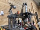
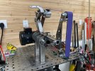
Here's how it looks to date:

IMG_0353.jpg
 
Last edited:
Today we finish up the metal fabrication work!

A bittersweet day. Happy to have the bulk of the fab complete, but I ran into some snags in the final stretch. I probably should've quit for the evening once I started struggling, but I'm too stubborn for that kind of reasoning. Seemingly simple parts ended up being a real bitch, and aligning the work table gave me a few extra grey hairs. I have been on a bit of a streak in welding the way I know I can weld, but sadly tonight ended that streak, and I actually had to grind -tan ugly weld and lay a slightly less ugly weld over top of it. Once I realized that was going to be my high water mark for tonight I accepted the bar-time weld. It lives underneath the work table anyway, so I'll only have my ego kicked occasionally if I happen to be dinking around with adjustments under there every so often. But.....I got it done. A few other challenges will be pointed out below, but it also looks like a big success in some features that really matter, namely tracking.

Started with the work rest tool arm and mount. Simple drill & tap. Same workaround with drill tooling as previously described.

IMG_0355.jpg

I like using the laser cut swivel stop and transfer punches to layout my holes.

IMG_0356.jpg

Now clamped to table and aligned to weld. This is the simple little piece that chapped my ass so badly. Started out with two tacks, then fit the work table and aligned everything to the flat platen. Not too terrible, just a bunch of fiddly tweaks & re-tweaks, but in the end the swivel stops didn't line up at 0 degrees and 45 degrees. This didn't sit well with my CDO (it's like OCD but in alphabetical order, the way it's supposed to be) and I cut a tack weld on the work rest mount and adjusted the fit. This created a decent sized gap in the final weld fit up of that mount to the swivel plate, and that created the ugly-ass weld I ended up getting humbled by. In the end, it was the right adjustment to make, but I probably should have paused and slept on it. There may have been an easier/simpler approach that I might have overlooked.

IMG_0357.jpg

And here it is, the finished work rest. 8"x15", a lot of real estate:

IMG_0358.jpg

IMG_0360.jpg

And here is the price I will have to pay for not being more patient:

IMG_0359.jpg

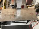
After struggling with that work rest mount weld/alignment circus, I was frustrated and a little heavy on the pedal welding the work rest tool post to the bottom of the work rest, and the extra heat warped the table a bit. I kick myself now for not clamping both ends down before welding it up, but it didn't cross my mind that such a large chunk of 1/4" plate would take a bend like that. It did. The good news is that it the apex is clear and linear, so I'm confident that I can correct it with a little targeted heat and gentle leverage. I'm working out a plan for that now, but if anyone has any suggestions, please post 'em up!

So with all the metal fabrication wrapped up, let's check in on where we are in cost so far for the grinder (all prices are shipped prices):


Revolution 4 Cut Kit w/weld seams removed: $595.00
Ameribrade wheel kit (2-2" wheels, 4" tracking wheel, & "TBD" accessory): 233.00

Running Total: $828.00
 
Last edited:
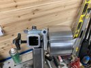
Gotta get that motor mounted to get the feel for the balance of the machine! Easy operation, just four bolts. My motor is the IronHorse MTR series premium efficiency AC induction motor, general purpose and inverter rated, 2hp, 3-phase, 208-230/460 VAC, 3600rpm, TEFC, 56C/HC frame, rolled steel, rigid base/C-face mount from Automation Direct. Fantastic company, super easy, lightning fast shipping. Ordered the motor and it was shipped FedEx arrived in two days. I had originally ordered one of their VFDs too, but it was backordered until mid September, so I cancelled and went another route. More on that later. Here it is with the motor mounted:

IMG_0361.jpg

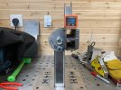
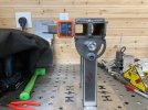
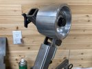
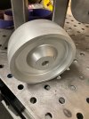
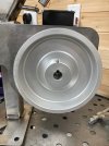
Heck yeah! Let's get a drive wheel on and see how this thing tracks with a belt! I chose a 6" drive wheel, because the math for SFM comes out perfect for what I want this grinder to be. 6" is not all that popular of a size, and I'm not sure why. The trend is for a 7" wheel and running over 6,000 SFM. That seems like a blade burner to me, maybe more suited for an industrial application. Thin stock and low volume doesn't scream that kind of speed to me. 5" is another popular size, and I'd choose 5" over 7" for making knives. But 6" delivers a high end of around 5600 SFM and is still well suited to low speed work too, in addition to being able to run large diameter contact wheels if I choose to in the future. Anyways, I had difficulty sourcing a 6" drive wheel that didn't cost as much as the rest of my wheels combined, so I plugged my nose and held my breath and bought a VEVOR (Chinesium) branded wheel off of eBay. I came quick, is nicely machined, and by all accounts appears to be a quality made part. Cool! Especially for $53.01.

IMG_0368.jpg

IMG_0369.jpg

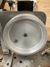
Wait..... that's not right....bottoms out before shaft is fully engaged. Turn it around?

IMG_0371.jpg

There we go! Wait...set screw. On the back side. No prob...............shit!!!

IMG_0370.jpg

No way to access the set screw to lock the drive wheel on. MOTHER$*@#^&%@!!!!!

So....I am returning the VEVOR drive wheel. The good news is that in the month since I bought this one, I see Jose Navarro over at Pheer Grinders has his 6" wheels back in stock. Great! I'd rather have a Pheer drive wheel anyways, even if it IS twice as much. So that's on order as of last night.

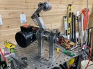
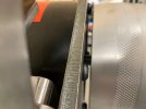
I still mocked up the drive wheel I have and hand, put on a belt, and run it by hand to see if I have any severe alignment issues from fabrication & assembly. No issues at all, and I got to play with the primary & secondary tracking planes to see how they affect belt alignment. Sweet setup, and I think I'm going to be very happy with it.

IMG_0363.jpg

IMG_0362.jpg

Oh, you forgot it's a tilting grinder that rotates on the same horizontal axis? That was what I didn't like about the Reeder. Beautiful machine, and a lot of well thought out features, but the way they chose to tilt the machine is kinda janky IMO, with the hinge and the kickstand, and the result is the grinder is lower in the horizontal position than it is in the vertical position. I don't know if that is a huge deal or not, but in my head it sure doesn't seem ideal. Especially if I'm going to take the time to station my grinder so it is ergonomically correct for me. I want that to be correct in all positions, not just one. Rotating on a center pinned axis allows that, where a hinge/kickstand setup does not. Personal preference, and YMMV, so please don't be offended if you own a Reeder. I know what kind of machines they are, and I have an idea of what kind of brilliant guy Don is. I looked very, VERY hard at them. This was just one feature that I didn't care for on his machines.

IMG_0365.jpg


So now we have a fab'd up chassis, complete wheel kit (will swap out drive wheel), and a motor. Let's check the ledger:

Revolution 4 Cut Kit w/weld seams removed: $595.00
Ameribrade wheel kit (2-2" wheels, 4" tracking wheel, & "TBD" accessory): 233.00
Automation Direct IronHorse MTR Series 2HP 3600 RPM 3ph Motor: 262.00
Pheer 6" Drive Wheel: 100.00

Running Total: $1190.00
 
Back
Top