PID forge upgrade (videos added)

weo

Joined
Sep 21, 2014
Messages
2,821
Hello all. It's time for me to put my forge back together and I think I'm going to make some upgrades. Here's a sketch of my original set-up:
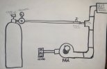
20191231_103241.jpg
And here's a schematic of what my plan is: Basic schematic.jpg
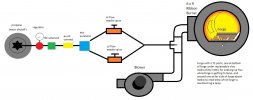
My initial upgrade idea was to install a NC valve right at the tank regulator connected to the blower wiring so that fuel is shut off when the blower isn't running, but that quickly morphed into adding the PID controller system. I don't intend on using this as a HT forge, I just want to try to improve my efficiency with fuel use.

This will probably be a WIP and I'm sure I'll have questions along the way. In fact, here's one: does it matter if I wire the NC solenoid in series or parallel with the blower?
Thanks
 
A power failure solenoid is a good idea. I don't quire understand the TC buried in the floor. Is it just barely below the floor?
 
The solenoid should be parallel with the blower, if both are 120 VAC and the supply is 120 VAC.

I don't understand the parallel needle valves, a needle valve is a pretty fine adjustment. I might consider injecting the gas just downstream of blower to provide a longer pipe run where air and gas are mixing.
 
I don't quire understand the TC buried in the floor. Is it just barely below the floor?

Hi Stacy. Happy new year. The reason for the 2 TC placements is that as you can see in the following pic, years ago, I WAY overbuilt this forge with 2" of refractory cement. Over the years, I've gotten used to this huge heat sink and how well this forge can hold a heat when putting large, cold pieces in. So I'm planning on having the TC in the bottom position (underneath whatever flux catching medium I go with.) This will allow the 2" of refractory to start to soak up some heat while the forge is heating up to my MIN temp setting. Then I plan to move it to the upper position to monitor my MAX temp.

The solenoid should be parallel with the blower, if both are 120 VAC and the supply is 120 VAC.

I don't understand the parallel needle valves, a needle valve is a pretty fine adjustment. I might consider injecting the gas just downstream of blower to provide a longer pipe run where air and gas are mixing.

Thanks Ken> (and happy new year to you as well). I was pretty sure the answer was parallel, but thanks for confirming.

The parallel valves are why I'm doing this. My plan is to be able to dial in the LOW flow so that the forge is still running but barely, and then when the temp starts to drop, the HIGH flow will kick in to bump the heat back up to the Max temp. I'm hoping this will allow me to maintain a reducing atmosphere for welding while making me more efficient with fuel use. I want the propane to fluctuate between low/high flow as opposed to completely off/on to avoid just blowing cold air into the forge (when off) and help maintain a consistent temp.

Oh yeah, I should mention that the sketches are NOT to scale....;)
 
Last edited:
Oh, I didn't look at the dwg enough, but that PID solenoid is actually a 3-way? Rather than OFF/ON, it switches from low to high. Makes sense. Be nice if you could have a two speed blower, low for low needle valve and high speed for high needle valve.
 
Oh, I didn't look at the dwg enough, but that PID solenoid is actually a 3-way? Rather than OFF/ON, it switches from low to high. Makes sense. Be nice if you could have a two speed blower, low for low needle valve and high speed for high needle valve.
Or have two blowers: one low flow always on, the other higher flow cycling with the PID demand?
 
Be nice if you could have a two speed blower, low for low needle valve and high speed for high needle valve.
Yeah, that might be a future upgrade, but I think I want to see if/how this works first....

Or have two blowers:
Which might be easier for me. I saw JT's thread and video on his setup using a variac or something-or-other, and while nice, is WAY above my pay grade....
 
You might consider using a single NC solenoid valve in the high needle valve branch and leaving the low side gas and air (with low flow blower) flowing all the time. The high side would only "add to" the gas & air flow of the low flow side. This one is only $11 shipped and rated for gas/fuel: https://www.amazon.com/dp/B018WRJYPY/?
 
Ummm ... now that I am thinking about it .... I am not sure a PID controller is the best thing to use here - especially if you are using the solenoid valve Ken recommends above. Most (??) PID controllers use a pulse width modulation to control the "level" of the output. This works for a solid state relay ... but with the solonoid like this, you are going to run up against its reaction time and not get truly modulated control (or you will effectively get always on/always off, or just burn the thing out). You might be better off going to an on-off thermostat type of controller ????
 
Ken,
He is building a version of my "Two-stage burner". There are much better schematics and detains in the Stickys on building a PID controlled forge.
The solenoid turns the HIGH flame on and off and has a needle valve in that line to set the HIGH limit for the flame. The by-pass needle valve is in the line that goes around the solenoid and keeps the low flame level going so the forge doesn't cycle from On to OFF , but instead cycles from LOW to HIGH.

Several of us tried running the blower on a two stage control but found it wasn't really necessary. That configuration is in my original plans in the stickys. Balance the flame for the HIGH level and it is fine at the LOW level, because they aren't that far apart.
 
Most (??) PID controllers use a pulse width modulation to control the "level" of the output.
Perhaps some PID do use a pulse width modulation (PWM) for control, but many (if not most) will also have a "OFF/ON" output that switches a SSR.

Since the blower speed doesn't have to be changed from LOW to HIGH, that sounds like a pretty easy to way to PID control a forge. This would be really nice if using the forge for normalizing and HT'ing. Since I'm only forging, does it really offer me all that much advantage over manually adjusting the forge for desired temp?
 
yep! if you are forging a metal that has a very narrow forging temp range, you can set your forge to a certain temp and you don't have to worry about the upper limit as much.
 
Perhaps some PID do use a pulse width modulation (PWM) for control, but many (if not most) will also have a "OFF/ON" output that switches a SSR.
p?
But ... if you set the output of a PID to on/off, then all you effectively have is an expensive thermostat ... so why spend the extra money, and potentially confuse yourself with a “tuning” process that means absolutely nothing?
 
But ... if you set the output of a PID to on/off, then all you effectively have is an expensive thermostat ... so why spend the extra money, and potentially confuse yourself with a “tuning” process that means absolutely nothing?
you can get pretty cheap set ups, like $40-ish... can you get a cheap thermostat type controller that will work with SSR/solenoid valves and type k thermocouples?
 
But ... if you set the output of a PID to on/off, then all you effectively have is an expensive thermostat ... so why spend the extra money, and potentially confuse yourself with a “tuning” process that means absolutely nothing?

I'm curious as well. Which is partly why I am posting this as a WIP . "Confusing" myself "with a 'tuning' process" is not a concern, but $ savings (if significant) is always a plus. If it's only a few bucks, however, then I'll go with a PID in anticipation of future upgrade to a HT oven if needed.

(The other reason for this thread is that many of the links and pics in the sticky are no good.)
 
Speaking of components, I was looking at this Auberns Universal 1/16 DIN PID Temperature Controller currently for $41.25:
https://www.auberins.com/index.php?main_page=product_info&cPath=1&products_id=106

but see they also have this 1/16 DIN PID Temperature Controller with built in SSR (2amp load) currently for $41.98:
https://www.auberins.com/index.php?main_page=product_info&cPath=1&products_id=237

I see that nickandersonart uses a 25A SSR in his build, so is the above mentioned built-in SSR too small?
 
I'm curious as well. Which is partly why I am posting this as a WIP . "Confusing" myself "with a 'tuning' process" is not a concern, but $ savings (if significant) is always a plus. If it's only a few bucks, however, then I'll go with a PID in anticipation of future upgrade to a HT oven if needed.)
I was running with the assumption (not sure if good or bad) that a simple thermostat is .... simpler.... than a PID, and hopefully cheaper and easier to set up. A quick search on line finds a few that are remarkably inexpensive, like THIS one at $12. but your issue around ability to upgrade to controlling a HT oven is a consideration...

I guess I have just seen several people struggle on this forum with getting a PID going, and simultaneously overly-relying on the "autotune" function without having the data to understand how strongly the thermal properties of their system affects the ability of autotune to work, and also how closely they can expect to control their system. If really close tolerance is not needed (like, variation of 5-10 degrees being acceptable), a simple thermostat is pretty bullet-proof....
 
I see that nickandersonart uses a 25A SSR in his build, so is the above mentioned built-in SSR too small?
Again - I would worry about using a SSR to drive your solenoid valve. That thing is going to click back and forth multiple times per second, or faster depending on the temperature. the controller might try to drive it so quickly that the physical inertia of the thing will not allow it to react quickly enough (leaving it mostly open, or mostly closed, depending on conditions - which is after all basically what a thermsotat does) - totally destroying the whole point of a PID based control. Not to mention I wonder if the rapid cycling of the solenoid will damage it.

a SSR is fine for something like a heating element where physical inertia is not an issue...
 
Back
Top