How To Electrical - star vs delta with 3ph 380V and vfd

ggGVf8A.jpg
I think ya'll might be missing the point the motor was originally wired to something other than VFD when the blue wire was used. Now, per the diagram in post #3 shows the motor is wired for a Wye (Star) connection with the blue wire connected. No idea how it was used originally.. For wiring to VFD the only wires needed are the 3 phases connecting to R, S, T and a ground wire connected to frame of motor.

Listen to JoeBusic, he seems very knowledgeable of wiring methods over there. Their methods are different than on this side (USA) of pond. Over here we tend to purchase VFD that take 1 ph 220 vac that uses 2 hot wires and a neutral. Over there they tend to use 1ph 220 vac that uses one hot wire and neutral. Of course ground wire for safety. The VFD is still going to put out 3 phases (wires) of voltage depending on voltage needed.

USA 3 ph motors tend to be dual voltage (230/460) that is wired in Wye (Star) mode. A motor has 6 coils giving 12 leads. Normally the T10, T11, & T12 leads are tied together inside the motor bringing 9 leads out putting the motor in the Wye wiring. I've seen a few 12 lead motors with no labels on the leads. That always requires sorting the polarity of the coils to wire up.

As Nathan said, lots of good knowledge in this thread, but also some errors so read with caution.
Update
I plugged it in and The breaker immediately tripped so I don’t know what the problem is…. but maybe it’s a grounding issue but of course I don’t know what to do….

R S are the 220 input.
U V W are the 3x380 output to the motor.

I appreciate all the responses and willingness to educate and help. But the language of electrical work is one I don’t speak well. Even less so than my weak French.
 
Last edited:
Update
I plugged it in and The breaker immed tripped so I don’t know what the problem is…. but maybe it’s a grounding issue but of course I don’t know what to do….

R S are the 220 input.
U V W are the 3x380 output to the motor.

I appreciate all the responses and willingness to educate and help. But the language of electrical work is one I don’t speak well. Even less so than my weak French.
1670086441969.png1670086441969.pngView attachment 2006042View attachment 2006042
Seems like you have a 3ph input
 
H HSC /// Though, the paint on your connection reveal something else. On the first look R and T are your input if it were single phase input. Usually they paint out the screws or connection for a purpose. Check all.

Edit: checked again and on several places it's confirmed you have a 3ph 380V input.
seems like you are correct, It should be 2S and its a 4T...
yet the rest of the label describes the product correctly...
I'll contact them Monday
 
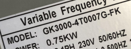
In post #8 the label of the VFD clearly shows (isn't that the VFD used?)
INPUT: AC 1PH 230V 60/60 Hz
Output: AC 3PH 0-380V 0-s500 HZ 2.5 A

It also shows the model as: GK3000-4T0007G-FK

Here's a link to the manual (This should be ok since it's educational)

Look on page 21 for wiring, the first terminals for 220V, 1ph would have L1 & L2 for input. In post #30 a photo is shown of this VFD shows terminals R, S, &T which match the 3nd row of terminals for a 3 ph input, except for the location of the "E" terminal which seems to be the Ground.

If that label in post #8 is from the actual VFD, and the photo in post #30 is of the actual terminal inside that same VFD, they don't seem to match - OR - am I missing something?
Post 8 is the label on my vfd
Post 30 is the actual terminal in the very same vfd.

I do not have an L1 and L2
I have RST. This seems to support the thought that I was sent the wrong vfd
 
There are inconsistencies in the manual. Contacting them for clarity is the best solution.
Edit: Seems just mislabeling. All else fits.
 
I suspect Joe is correct, just miss labeling. On my Chinese VFDs it shows the RST terminals and to use R S T for 3 ph input, BUT to use R & T for 220V 1 ph input with the two "hots" going to R & T. That just might be the case with your VFD, with the one "hot" 220v going to the R and the neutral going to "T". You said when connected to R & S it tripped breaker. Checking with tech support would be the "safe" way to confirm the R & T connections.. I might be tempted to move the "S" wire to "T" and try - should only trip breaker again if it doesn't work?

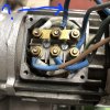
The "Blue" wire that's connected to the middle terminal on top row in motor connection box has been removed? OR lat least not connected to anything? If that wire is connected to anything that would most likely trip a breaker.

The VFD's U, V, & W output terminals are connected to the bottom row of terminals in the motor connection box? I'd sure be tempted to try it - You do have a fairly small breaker? Not a 20 or 30 amp breaker?
The BLUE wire is not connected to anything, correct.

yes I could try T but I think at this point I'm not going to do anything until I can get a confirmation from the company that I have a mislabeled incorrect VFD

"U, V, & W output terminals are connected to the bottom row of terminals in the motor connection box". yes correct. see post 1 picture
brown, black, grey colored wires

I have a 16A breaker
 
I suspect Joe is correct, just miss labeling. On my Chinese VFDs it shows the RST terminals and to use R S T for 3 ph input, BUT to use R & T for 220V 1 ph input with the two "hots" going to R & T. That just might be the case with your VFD, with the one "hot" 220v going to the R and the neutral going to "T". You said when connected to R & S it tripped breaker. Checking with tech support would be the "safe" way to confirm the R & T connections.. I might be tempted to move the "S" wire to "T" and try - should only trip breaker again if it doesn't work?

The "Blue" wire that's connected to the middle terminal on top row in motor connection box has been removed? OR lat least not connected to anything? If that wire is connected to anything that would most likely trip a breaker.

The VFD's U, V, & W output terminals are connected to the bottom row of terminals in the motor connection box? I'd sure be tempted to try it - You do have a fairly small breaker? Not a 20 or 30 amp breaker?
So you are correct. It’s R and T
I found it on their YouTube video and sure enough it works
lnfa9TY.jpg

pQtv4HF.jpg


FHQ2m5G.jpg
 
Jesus christ. Not sure if any electricians have posted here, so maybe I'm the first. Are you really looking for electrical help on a knife forum? If you cant even determine your source voltage, you have no business messing around with this stuff. I guess you deserve whatever happens to you or your equipment. Smh.
 
Last edited:
Jesus christ. Not sure if any electricians have posted here, so maybe I'm the first. Are you really looking for electrical help on a knife forum? If you cant even determine your source voltage, you have no business messing around with this stuff. I guess you deserve whatever happens to you or your equipment. Smh.
In Europe electricity is simplified to US. This is a basic connection. Just follow the labels. But this one was mislabeled so a confusion have risen.
 
So you are correct. It’s R and T
I found it on their YouTube video and sure enough it works
lnfa9TY.jpg

pQtv4HF.jpg


FHQ2m5G.jpg
Nice. They should even fix their manual for this, not just the VFD label. But all things went good. :)
Now comes the tricky part. Take your time and go thru the manual. A lot of goodies are there. Many things can be setup to make the work flawlessly. One thing that is almost a must is get a switch for forward-reverse drive. Take care of harmonics (not hard) and use vector drive if it works best. All else is optional and can be reset anytime. VFD is a machine from God. :)
 
Glad you got it working - I saw that "red" terminal with no screw but thought perhaps a screw was removed or left out.

Sounds like looking for info about electrical/VFD on a "knife forum" actually worked with all of us "talking it thru" helped you find the solution. Agreed with Joe, a Forward/Reverse switch is well worth the effort. I use reverse a good bit.
 
I am of JW with over 20 years in most major fields of industry. My customers always had access to 3 ph service from above the weather head. I just learned about hybrid drives when I built my 72.
When using a hybrid drive to power any three phase motor with 110 or 220v supply, you will choose the low voltage configuration of windings.

Your T1, T2 and T3 are tied to T7, T8 and T9, respectively. T4, T5 and T6 are tied into a single connection.

L1, L2 and L3 will always tie into T1, T2 and T3, respectively. Regardless of connecting for high or low voltage.

I can't think of anything I want in delta, other than a transformer. The issue of Delta vs Wye seems to not really apply

480v is high voltage
220v is low voltage.
Your VFD is fed two phases of 120 volts that gets stored into capacitors, that are like temporary batteries. The output is controlled by being able to use diodes as gates to apply the voltage onto three phases at any rate commanded.

Compare that to using a dimmer switch for speed control and image the difference in heat!!!!!
 
In Europe electricity is simplified to US. This is a basic connection. Just follow the labels. But this one was mislabeled so a confusion have risen.
Umm... no. Electrical theory is the same everywhere. We have 3phase with a high leg here in the US and most of our old plants and warehouses operate on wye or a combination of both delta/y. When you say things like "I've got 230 from phase to neutral, " when you don't even know if you have a neutral, you sound like an insurance company's dream.
 
Umm... no. Electrical theory is the same everywhere. We have 3phase with a high leg here in the US and most of our old plants and warehouses operate on wye or a combination of both delta/y. When you say things like "I've got 230 from phase to neutral, " when you don't even know if you have a neutral, you sound like an insurance company's dream.

Easy there bro. I wouldn't get too testy.

I misunderstood something JoeBusic said earlier and I wondered if he knew what he was talking about, but fortunately I noticed my misunderstanding before calling him out. I think he might actually know what he's talking about pretty good.

I asked the op if he had 230 that was two 115 or a 230 and a neutral to get a better understanding of what was being fed that VFD. His 230 is a 230 and a neutral, which is not how it's done here in the states.

Everybody here understands there is a neutral.

There is some confusion why it is attached here:

dAuOYQL.jpg


Any thoughts what that does? You're an electrician. Why is that neutral there? What does it do?
 
Easy there bro. I wouldn't get too testy.

I misunderstood something JoeBusic said earlier and I wondered if he knew what he was talking about, but fortunately I noticed my misunderstanding before calling him out. I think he might actually know what he's talking about pretty good.

I asked the op if he had 230 that was two 115 or a 230 and a neutral to get a better understanding of what was being fed that VFD. His 230 is a 230 and a neutral, which is not how it's done here in the states.

Everybody here understands there is a neutral.

There is some confusion why it is attached here:

View attachment 2006998


Any thoughts what that does? You're an electrician. Why is that neutral there? What does it do?
Let me start by saying I don't know how these motors are wound, and while I do have a background in electronics, my experience is with radios and radar not motors.

My hypothesis is that the three joined leads might make an unused coil?

If so, then the motor spinning would induce a voltage on that coil. The neutral wire would give that induced voltage somewhere to go, other than back into the working coils.

Not having the neutral there wouldn't stop the motor from working and really the only benefit is that the unused coil wouldn't be fighting the working coils, this eliminating an extra source of heat.

Like I said earlier, I'm not an electrician, just an idea I had.
 
Back
Top