First Grinder Build Q's

Joined
Dec 9, 2015
Messages
392
The time has finally come for me to build myself a 2x72. After a lot of window shopping I've decided that I really like the dcknives style grinder and want my build to be based on this, but with step pulleys. So far all I have is a motor and a rough plan. I also have plenty of tools and enough experience to handle the actual construction. I do have some design questions though.

Some background that I hope will be helpful:
I'm a hobby maker, I aspire to be good enough to make sell-able knives but I have no intention of going pro.
I'm working out of a shed with a single 110v/15a outlet, which is why I went with a 1hp (13a) motor. I'm renting so this is not going to change for at least a few years.
My primary interests are traditional pocket knives and kitchen knives, but I like making any sort of knife or tool that I might need. I'm the kind of person who sees something cool and my first thought is "How can I make that?" so I'd like to keep my grinder as versatile as possible.

On to the questions!

1) The dcknives grinder has a vertical, telescoping tracking arm. The KMG style lever arm seems like it would be more ergonomic, but will there be enough real-world difference for it to matter? Any differences in grinder performance or trickyness of construction?

BG-272%2BmetalworkBOM.png


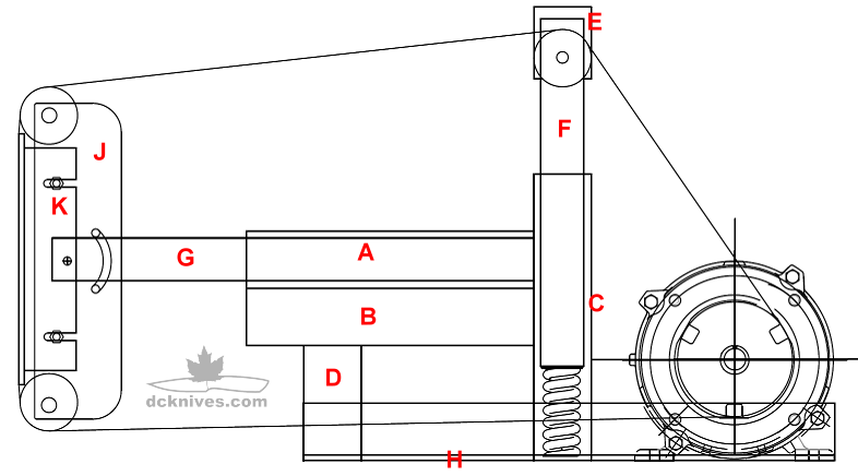
2) When I have the shaft behind/below the grinder with a step pulley on one end and drive wheel on the other, will I need two pillow block bearings or will just one do it? Even if just one will do it, will two be better?

3) I made a spreadsheet of potential wheel/pulley combos, what do you guys think of these speeds for an all around knife making (steel, brass, wood, G10, bone, etc) grinder? My current 1x30 runs at (claimed) 3260 SFPM. With Blaze belts it cuts steel well enough, but it burns the heck out of wood and gets brass very hot very fast.

The SFPM column is highlighted. I'm worried that trying to go too fast on the highest speed will bog the motor. I can bog my little HF sander just by looking at it the wrong way and for all this time and money spent I don't want to have to worry about that under normal use.

4vNXxlW.jpg


Thanks for reading!
 
To answer the pillow block bearing question, you need two regardless. PB bearings "float" to help with alignment, and if you only have one, it will move all over the place on you.
As for the tensioning mechanism, I've long thought that a pneumatic cylinder in lieu of a spring would be a good option for this design. The kind that switches on/off with a regulator. It's pricier than a simple compression spring, but I think it will work better for the design.

The problem is, too weak of a spring won't give enough tension to the belt, and tracking will suffer. Too heavy, and it's hard to push down. Now I did see where somebody made a levering mechanism to pull the tracking arm down with a lever arm, but I can't remember for the life of me where I saw it, or who did it. If I find the video, I'll post it. It was pretty slick.
 
Ohhh.... it was DC Custom Knives... DUH!


This is a much better design option, IMO, as it allows for a much heavier spring.

That said, I'd still like to see a small two way pneumatic cylinder and something like a lever valve to turn it "on" or "off". Regulated to about 90 lbs, I think it'd be pretty slick. I believe they make a cylinder small enough to fit the existing design with a little forethought, though I haven't looked into enough to say for sure.
 
A cylinder like this?
Photo%20Apr%2005%2C%2012%2002%2056%20PM.jpg

Something like that. ;)

I've seen some pretty small pneumatic cylinders at mcmaster carr that would probably fit inside a 2" square tube. Length might be a limiting factor, but you could probably find one that would do the job. I don't imagine it would need more than a 2" stroke, and would probably work with even less.
 
I made that exact grinder following the plans. I didn't like the tension spring so I installed a pivot arm and used a gas shock for tension. I like it way better and its really easy to change the belt. I also added multiple pins to mount the gas shock to to change the tension. I also used a 3hp DC treadmill motor.

If I did it over again I'd use flat bar welded into square tubes to get a more precise fit.

https://www.flickr.com/photos/160810863@N04/albums/72157669077585988


Thats a good idea, I think I'll do the arm with multiple spring mounts.

Could yoy add shims to your existing one for a tighter fit?
 
I welded some small tabs on the tool arms at the corners. I then ground down the tabs for a tight fit. Work well enough. I've heard of some people using pop cans or plastic shims.

You'll see in the second picture that I made the grinder to be tilting. It works very well but I haven't really had a need for that yet.

The hardest part is squaring everything up but it's not too difficult. Minimal welding is key to avoid things being pulled out of alignment. I went too crazy because I wanted to play with my new Tig. My motor is mounted to a rubber pad. I put a belt on the platen and motor without the adjustment roller. I could then crank down on one side or the other to squish the rubber to make sure my pulleys were aligned. Heavy springs would work. I got it to run true without the adjustment pulley first. I usually take the buffing wheel off because it causes a bit of vibration but not much.

You'll also want to ground the belt. Dan's site has a build for this with a wire brush. I kept getting shocked thinking it was my wiring not realizing it was static. It's much worse with a glass platen. At 8000 ft/min it builds static incredibly fast.

I also moved the location of the gas shock to close to the pivot as it was too strong but that isn't shown. I used this shock:

https://www.amazon.ca/gp/product/B074V5BFNW/ref=oh_aui_detailpage_o08_s00?ie=UTF8&psc=1

At 71 Lbs they are very stout. You should be able to find something similar at an auto parts store. Just look for tailgate shocks. I think strongarm is a common name.

Next you'll be building the heat treat oven from his site like me. I did a build page on that.
 
When it comes to static electricity a lot of people just spray the underside of the belt with laundry static remover.
 
Here's a cylinder that would probably work:
https://www.mcmaster.com/#6498k654/=1cw03x3

It would fit inside a piece of 1.5" square tube pretty easy, and give you up to 90# of pressure if you regulate it to 100 psi. You might have to get a little creative with mounting, though that shouldn't get too complicated, and then you'd just need the appropriate fittings, a 4 way valve, a possibly a regulator. Obviously you'd need to account for clearance for your hose fittings, however that needs to be.
In fact, you could simplify things even more with a single acting cylinder that has a spring retract. Then you'd just need an "on/off" toggle with an exhaust, and you'd only need to drill your 2" lower tube for the lower air fitting. The setup would be a bit cheaper and easier to build.

Something like this one:
https://www.mcmaster.com/#6498k534/=1cw0au3
 
If I did it over again I'd use flat bar welded into square tubes to get a more precise fit.
Have you ever tried to weld “flat bar” into a square tube? First it’s never flat. It’s bowed n twisted. Second it’s hard/impossible to get 4 pieces into a “precise” square. Third once you laid one weld onto it it’s gonna pull and bow and bend. You’d never get it as square as a piece of tubing! How did you cut all your pieces? Wall thickness? Something isn’t right if you’re thinking flat bar would be more precise.
 
I was actually thinking about drilling and taping. It'd be a pain to tap all those edges but you wouldn't need to worry about the inside seam that square tube has. Something like this or kmg.
https://www.google.ca/search?q=2x72..._AUIESgB&biw=962&bih=601#imgrc=_QZ6dFs6osp_gM:

Your right about trying to weld something square though.

Here's a good video of someone with way more skilled than me trying that exact thing. He ends up with an awesome finished product though.
 
Last edited:
I agree, that guy’s grinder is a beast! I built a tubing based 2x72 and it turned out ok. It works and tracks ok, part of the problem is the fit between the square stock I am using for tooling arms and the inside of the tubing. The tubing does not have square corners, and the tool arm does.
This has lead to inconsistency in the mating surfaces, thus some wiggle.
Make sure that the seam of your tubing, if you end up using it, is not on the side that your tool arm will push up against.
I have read that you should have the seam opposite, so the arm is being pushed away from the seam, but not sure if that is gospel, or just preference.

I have 2 grinders built with tubing. If you go this route, def stick the seam the opposite side at the wheels. That way when the tooling arm is tightened it's going against a flat surface. Mine tracks perfectly fine. I used 2"x 2" x 1/4" for the grinder and 1.5" x 1.5" x 1/4" for the tooling arms. It is slightly a PITA to grind the seam down, but a harbor freight finger grinder makes pretty easy work of it. However if I ever build another one, I'd use plate and bar stock and drill and tap everything.


grinder.jpg

grinder2.jpg

grinder3.jpg
 
Last edited:
With a 1hp motor, would simply adding a rheostat help with the speed problem?

I am not far off from making a grinder too. I found one on craigslist used for bicycle tubing, so going to need a lot of customization. But it uses a pneumatic cylinder, and it keeps things tight, but I hate having the compressor on too. I can take pictures of it when I get home tonight.

Are you going to make your own platen and other tool arms or buy?
 
With a 1hp motor, would simply adding a rheostat help with the speed problem?

You can't use a rheostat on an induction motor to change rpm. The rpm is increased and decreased by raising and lowering the hertz frequency not the voltage like a rheostat.
 
Can't use a rheostat with these type of motors. Single phase motor, you need pulleys. Three phase motor you can go VFD.

I had my mind set on this style of belt grinder for a couple years. But so much happened in that time...my understanding, my skill level & my tool gathering. So when the time finally arrived, I built mine using cold rolled 1018 bar stock, and 2024-t3 Billet. And it's one stout piece!

The dcknives design looks like decent setup. I wouldn't go crazy with the tensioning system on a square tube build though. The compression spring is so simple and it works! Going pneumatic just seems like a fix for non existent problem, imho. But good luck with it my friend! :)
 
Here's a cylinder that would probably work:
https://www.mcmaster.com/#6498k654/=1cw03x3

It would fit inside a piece of 1.5" square tube pretty easy, and give you up to 90# of pressure if you regulate it to 100 psi. You might have to get a little creative with mounting, though that shouldn't get too complicated, and then you'd just need the appropriate fittings, a 4 way valve, a possibly a regulator. Obviously you'd need to account for clearance for your hose fittings, however that needs to be.
In fact, you could simplify things even more with a single acting cylinder that has a spring retract. Then you'd just need an "on/off" toggle with an exhaust, and you'd only need to drill your 2" lower tube for the lower air fitting. The setup would be a bit cheaper and easier to build.

Something like this one:
https://www.mcmaster.com/#6498k534/=1cw0au3

I've thought about using these since I have a pile of them. Why DA? This is just spring return. Air on - extended, air off - retract.

20180518_093751.jpg
 
Back
Top