Heat Treat Oven Issue - Low Max Temp - Auber 2352P

Joined
Nov 15, 2005
Messages
1,198
Hey guys, I'm messing around with a DIY HT oven in my shop and have been having some issues. For some reason my oven is maxing out around 1315F.

I was hoping someone may have some ideas on what my problem is. I'm hoping it's just my lack of experience with this Auber 2352P controller.

Build:

Chamber Size = 5'' tall x 6.5'' wide x 18'' long
Chamber Volume = 0.3385 ft3
Chamber Construction = soft fire brick plus 1'' ceramic blanket
Elements = 16 AWG Kanthal A1 wound to a 0.4766'' diameter
Element Resistance = 17.8 ohms
Oven Electronic Specs = 240V, 3236 watts, 13.5 amps
Watt/ft3 = 9559

Elements are run in 2 U-shape paths along the two inner walls (none-along the back). These two coils are wired in series with a 10 AWG jumper outside of the oven in the back. Ohms are confirmed @ 17.8 with meter. The total path length of both sides combined is 71 inches (total stretched coil length)

Wiring diagram:


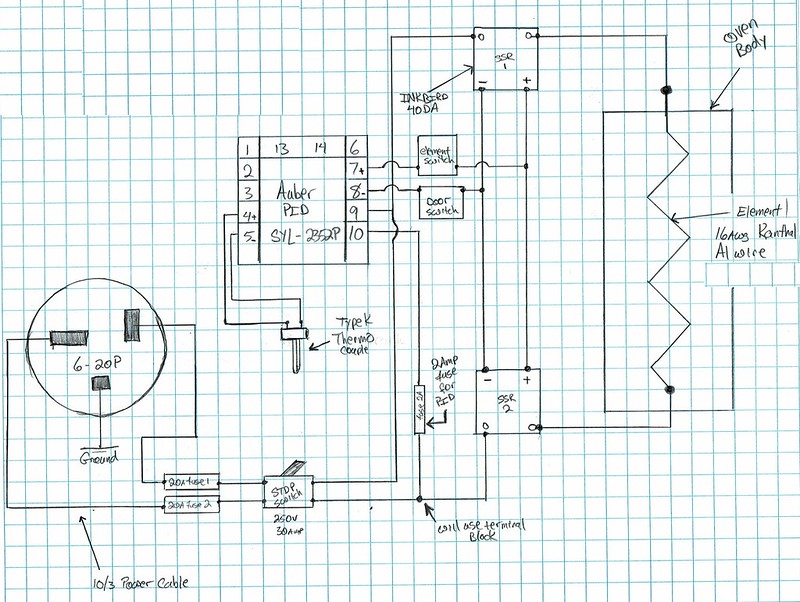
~12' of 10/3 power cable running from a dedicated 20 amp 6-20P. All oven internal box wiring is high temp 12 AWG and the runs to the elements are 10 AWG high temp.

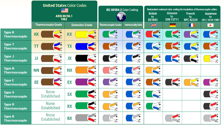
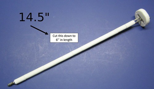
I cut this 14.5'' thermocouple down to ~6'' in length... not sure if that could be an issue? I ran new type K TC wire from KilnParts.Com. It appears to be reading the ambient temperature accurately before start up.


Auber 2352 P:
I've tried a bunch of different PID configurations in the controller including a straight proportional control with I and D zeroed out (P60,I0,D0). I figured this would ramp quickly for a test. It still maxed at 1300. The graph is for the default settings for the PID values:


If also tried to AT from both the 1300 range and zero without better results.

The settings on the alarms have all been set to their maxes (not sure if that matters anyway... if it's alarming or not that is?... since I don't have an alarm wired into the PID).

"COOL" is set to 10 which should mean it's reading in F

Program:

C01 = 1975
T01 = 1
C02 = 1975
T01 = 150
C03 = -1
T03 = -1
repeated to 30


Thanks for any help guys! I basically have an expensive door jam at this point... ;)
J. Keeton
 
I'd give Auberinstruments a call. They have really good tech support from what I hear.

Are you sure the TC is a "trimmable" type?
 
I suspect it is the thermocouple. Did you weld the junction after trimming it? If I remember right, the thermocouple wires are two different alloys. Can't hurt to double-check that it is hooked up correctly. You could test in ice water and boiling water, or use a lighter to see if you can max it out. Also, if you open the door and take a look inside, you can probably tell from the color of the oven walls if the thermocouple is reading low.

I'm sure it won't be a door stop for long. Looking forward to the build video.
I hope that he did not cut cut TC from junction side................
 
I'd give Auberinstruments a call. They have really good tech support from what I hear.

Are you sure the TC is a "trimmable" type?
They are "trimmable" type .They measure in first inch on junction ...........you can cut from other side as much as you need ......or buy long one as you need
 
On the TC I didn't mess with the junction at all. Figured that's the end where the magic happened. I cut from the side with the ceramic mounting plate, then re-installed the ceramic mounting plate. I used to use that TC in my forge some to gauge temps and it was capable of reading higher temps then. Ice and Boil would be a good verification test for sure.

Feels like there is a "governor" on this thing, which is what made me think it was possibly something going on with the controller.

For reference my set points are as follows:

ALM1 - 5000
ALM2 - -1000
HY-1 - 9999
HY-2 - 9999
HY - 0.3
AT - 3
I - 0
P - 50
D - 0
t - 2
SN - 0 (type K)
DP - 0
p-sl - -100
P-SH - 2500
Pb - 0
oP-A -0
outL - 0
outH - 100
AL-P - 17
Cool - 10 (fahrenheit)
Addr - 1
bAud - 4800
Filt - 0
A-M - 2
Lock - 808
EP1-EP8 - Default - none
 
Last edited:
On the TC I didn't mess with the junction at all. Figured that's the end where the magic happened. I cut from the side with the ceramic mounting plate, then re-installed the ceramic mounting plate. I used to use that TC in my forge some to gauge temps and it was capable of reading higher temps then. Ice and Boil would be a good verification test for sure.

Feels like there is a "governor" on this thing, which is what made me think it was possibly something going on with the controller.

For reference my set points are as follows:

ALM1 - 5000
ALM2 - -1000
HY-1 - 9999
HY-2 - 9999
HY - 0.3
AT - 3
I - 0
P - 50
D - 0
t - 2
SN - 0 (type K)
DP - 0
p-sl - -100
P-SH - 2500
Pb - 0
oP-A -0
outL - 0
outH - 100
AL-P - 17
Cool - 10 (fahrenheit)
Addr - 1
bAud - 4800
Filt - 0
A-M - 2
Lock - 808
EP1-EP8 - Default - none
That makes a lot more sense, cut it from the other side. I hope you can figure out what's going on. FWIW, I have the non-programmable version of that controller and it has been working flawlessly. I am also using an Auberins thermocouple (WRNK-191) without any problems so far.

I see you have a door switch in your design that interrupts power. Could you tell me what model that is and where you got it? I am slowly planning to build a bigger furnace and trying to get a parts list together.
 
Ok, after looking at the manual - two things.

first, you don’t say (I think) what your set point is ... is it much higher, like 2000?

second, this is one of those “fuzzy logic” controllers, so it is Ill-defined what the proportional band is. The manual says “ larger p values give faster stronger responses”. With your p value of 60 out of 9999, that is WAY small, and might be giving you the equivalent of a huge proportional band, which would explain the undershoot. Try maybe p=1000 and see if response is better. (That does not explain why auto tune appeared not to work, but at least it is something to try...)

with your power, this thing should work ... don’t despair !
 
Ok first thing I would check is the SSR’s. Are thy being cut off at that 1315°? Just look at the light on them and if the red led is off then thy are not on. Another thing I would check and this might sound dumb, Check your door switch. I built mine to cut power when the door is fully open to prevent this issue. Depending on how your door switch is set up the bricks can expand and push on the door just enough to cut the switch contacts. This is usaly only an issue if the contacts are barely touching. But you would be surprised how much things grown when thy heat up.
 
You did install the TC with correct polarity ... and used the correct polarized type K wire to the PID. If one of those junctions is wrong, it will not work right.
 
The temperature/time curve looks about the shape I'd expect with constant (though possibly low) power. I don't know the Auber controller, but looking at pictures and the manual, it seems the output indicator is the bottom one on the left. Is it steady, or flashing, when heating?
The controller controls by switching the output on and off. There will be an output cycle time ("t" in settings, default is 2 seconds for SSR) and the controller feeds the output for some proportion of that cycle. Full power will be 100% of the cycle, so the output light will be continuous at full power. At half power, it will be on for one second and off for one second on the default 2-second cycle time.
Digressing: If the cycle time is 30 seconds, then at half-power, the light will be on for 15 seconds and off for 15 seconds. This tends to give a saw-tooth time/temperature profile. It is one of the main reasons for using SSRs, which can switch fast, instead of relays/contactors, which need a longer cycle time. The other reason is noise: contactors clunk in and out. SSRs are silent.
Digression over: If the output light is continuous during heating, you can be fairly sure the problem is with either the elements not providing enough power to heat the oven properly, or with the temperature measurement not displaying the correct temperature.
Your settings above show the controller set to typeK input (Sn=0), so the sensor type is correct. Are you sure it is set to degF though? I couldn’t work out how to do that from a quick look at the .pdf of the manual. If it is set to degC, everything would seem fine operationally.
If you want to check the thermocouple wiring, use a hairdryer on the terminal block where the cable connects to the thermocouple wires. The cable should be 2 different compositions that match the thermocouple legs. When connected correctly, there is no junction of different metals at the terminal block. If you have got it wrong, there will be a junction at each terminal, the opposite way round to the measuring junction. If you warm up the connector block (but not the oven) and see a sizeable change in indicated temperature, you’ve got it connected wrong.
 
Ok first thing I would check is the SSR’s. Are thy being cut off at that 1315°? Just look at the light on them and if the red led is off then thy are not on. Another thing I would check and this might sound dumb, Check your door switch. I built mine to cut power when the door is fully open to prevent this issue. Depending on how your door switch is set up the bricks can expand and push on the door just enough to cut the switch contacts. This is usaly only an issue if the contacts are barely touching. But you would be surprised how much things grown when thy heat up.
I've had that exact problem with my door switch as well. Took me a while to figure out.

With the smooth temperature vs. time curve, I'm not sure if anything is cutting off though.
 
Well guys, thank you greatly for all your suggestions! Yall were right about the TC being cross wired. (Thanks T timgunn1962 Stacy E. Apelt - Bladesmith Stacy E. Apelt - Bladesmith !)

When I applied heat via a heat gun to the TC block on the outside of my oven the temp would go down.

I swapped the leads on the TC block, then swapped the leads on the TC terminals on my PID. this got it reading right. At this point the heat gun on the outside will not change the temp.

I then reset the PID to stock set points and re-ran a test. In the same amount of time it ramped up to ~1500.


Once I got to 1500, I let it stabilize, then ran the AT function. This changed my PID from i1000,p500,d120 to i918,p16,d9.

If I can carve out some time, I'll re-run a third test tomorrow with the new "auto-tuned" set points. I hope it will ramp faster with these new set points.

----------------------

Once again, thanks for the help guys! Yall saved my bacon. I'm disappointed at myself... the oven got way hot while I was trying to figure out how to get it above 1300F.... My door was too tight and I cracked a brick while jacking around with it... will need to repair now. Like JTknives JTknives said, I'll likely need to add a spring mechanism to my limit switch due to expansion as well.

Cheers yall!
 
BTW, a quick test to make sure that the TC leads are right is done with a magnet. The negative side on a type K thermocouple (or wire) is magnetic.

Here is an older post I made on the color codes for TC wires ( red is opposite in different parts of the world):

In type K TC wires the cover is yellow. Inside are two leads - Red is negative and yellow is positive

Thermocouples are polarized. One lead is made from alumel. It is magnetic and is the negative lead ... which connects to the red wire in type K TCs . The chromel lead is not magnetic and is positive .. thus connecting to the yellow lead.

All other plugs, sockets, and TC blocks are polarized, too. Look for the + and - marks.

This is the color code chart for TC wires:
https://www.thermocoupleinfo.com/thermocouple-color-codes.htm
color-codes.jpg
Son of a gun... here I thought the red was positive. Last night I was wondering why having it “backwards” was working!
 
Son of a gun... here I thought the red was positive. Last night I was wondering why having it “backwards” was working!
Well, if you look at the chart Stacy posted you'll see Red is positive with some countries and USA red is negative. So, is red positive? All depends.
 
Allrighty guys, I ran a test with the PID values from my 1500 degree auto-tune. I figured I'd take this guy up to 1975 and run the AT again.

I'm curious on what yall thought about the results. Is a ramp to 1,500F in 37 min and a ramp to 1,975F in 88 min normal? Seems long to me, but this is my first oven...


As yall can see the difference between the stock i1000p500d120 and the AT results of i918p16d9 really don't change the ramp very much.
 
Back
Top