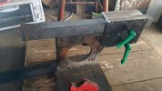
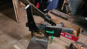
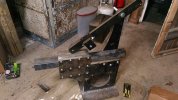
Grinder plans

and it looks like you'll still get about 1 - 1 1/2'' of ''lift'' at the wheel. that will be plenty.
Yes. I figured any more than the stroke of the gas shock was over doing it. The shock stroke is a hair over 2" the cam travel is a hair under. It also makes the engagement/ disengagement movement pretty much a push/ pull movement.

Sent from my ASUS_Z01BDC using Tapatalk
 
I uploaded revised plans to the link on the first page. The original drawing had 3 layers, this one has just one, so there should be less confusion with the water jet person. Enjoy!
 
That looks great. I'm looking forward to seeing one in the flesh.
I think I'm going to build an over center can for mine.
 
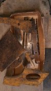
So I got my steel back from my buddy. The cutting wasn't perfect, as detailed below. And he just handed me a big box of steel parts. The steel and the water jetting was free, so I don't mind having to do some tweaking.
P_20170507_230717_vHDR_On.jpg
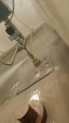
First, I wanted to finish drill and tap the left side plate. The holes get tapped for the bolts that hold the pieces that form the two tool arm pockets. The alignment is critical and I wanted to know right away if there was an issue. To keep the small cut outs from the water jet cut holes from falling down into the water jet cutting tank, they are retained with a small tab. The pieces knock out really easily with a punch, but the tab remnant needs to be removed by drilling with a 1/4"-20 tap drill. This may not be an issue with other water jet setups, but hey, it's free.
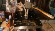
P_20170507_230749_vHDR_On.jpg
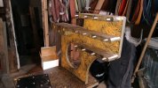
Next is the spacers that form the pocket. There are 3 long ones and 6 smaller. The long ones are the separators for the top and bottom pocket, the smaller ones form the top of the top one, and the bottom of the bottom one.
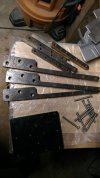
P_20170507_232356_vHDR_On.jpg

Finish drilling the 1/4" through holes on the spacers.
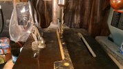
P_20170507_232839_vHDR_On.jpg

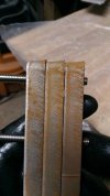
The water jet is supposed to make a nice clean edge. Something was off on the machine making it think it was cutting thinner material than the 1/2" plate used. This caused some edges to be uneven. Did I mention it was free? ;)


P_20170507_233640_vHDR_On.jpg
I bolted the spacers together with the side plate to even them out with the profile of the tapped side plate. This goes to the outside and will not effect the pocket dimensions, I just want it to look nice. I will true up the interior faces if I have an issue with the tool arm clearance. Good thing I already have a 2x72 to make quick work of this.
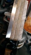
P_20170507_233803_vHDR_On.jpg


Next is a trial fit up of the pockets- looking good.
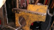
P_20170508_000608_vHDR_On.jpg
P_20170508_001450_vHDR_On.jpg
Because we are super classy here, I had my logo cut into the main upright.

P_20170508_001459_vHDR_On.jpg
My fancy pants knobs to lock the tool arms fit well.
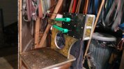
P_20170508_001933_vHDR_On.jpg
 
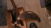
What should have been a semi-circular track to allow tilt of the platen somehow turned into more of a "D" shape. I think this is due to the water jet logic, NOT the DXF file. I think I can make it work with a large washer on the side opposite the tool arm.

P_20170508_002837_vHDR_On.jpg
 
What should have been a semi-circular track to allow tilt of the platen somehow turned into more of a "D" shape. I think this is due to the water jet logic, NOT the DXF file. I think I can make it work with a large washer on the side opposite the tool arm.

View attachment 706136

Kevin, cut you a piece of flat bar that has 2 holes one center of front hole and second center of back hole long enough to create one long washer say 1/4" stock. Should be good to go and give you plenty of support over the large hole looking thingy in the back.. lol.
 
Kevin, cut you a piece of flat bar that has 2 holes one center of front hole and second center of back hole long enough to create one long washer say 1/4" stock. Should be good to go and give you plenty of support over the large hole looking thingy in the back.. lol.
I was thinking the same thing. I may fabricate a new, longer D plate altogether down the road. Now that I'm doing a lot of kitchen knives, a longer platen is not a bad thing.
 
I was thinking the same thing. I may fabricate a new, longer D plate altogether down the road. Now that I'm doing a lot of kitchen knives, a longer platen is not a bad thing.

I def like a larger platen having only had one. My platen plate is 12", 16" axle to axle. If I make another grinder I may go up to 18" axle to axle. I can't on the current one as my tooling arm is already all the way as far in as it will go.
 
I purchased the 1.5" square bar for the tooling arms. That stuff is NOT light. Luckily, I have a well stocked welding shop/ metal supply company close by. I also picked up a cutoff of a 5" schedule 40 pipe and a 10" square- 1/4" plate for a vertical quench tank, but that's another project. I decided to weld the vertical to the base plate. The ability for me to drill the holes into the vertical plate and tap them straight was iffy. The motor will also act as reinforcement of this connection, so I think I will be good. My welding is not the best (note massive understatement). But it's square and solid. The tooling arm pockets are a good fit for the arms. Just enough room that the arms slide without binding. When tightened with the green knob, you can lift the whole thing with the arm and it doesn't shift. so it seems like that will work. I am on the fence about painting it. I am leaning towards cleaning it up and painting it assembled. I was going to disassemble to paint, but I don't think that's necessary. thoughts?
P_20170509_075745_vHDR_On.jpg
 
Last edited:
I don't have anything to add really but watching this anticipation. I've built a few grinders and I dig your design. Tell your water jet buddy to slow that machine down though! Those edges also known as kerf are from him running it fast. If he slows down much cleaner straighter edges.

I say powder coat it! But I hate rusty tools
 
Just a comment for those who want to use long platens or really large wheels - use a 2X90" belt. That way the distance from the tension and drive wheels to the platen or contact wheel isn't so close.
 
I would paint or powder coat for sure. Other than that, it's looking good so far!
 
Thanks all. On the water jet, he said he used the parameters set in the machine. Basically just put in the thickness and type of material. He got it to cut the rest out cleanly by telling the machine the plate was thicker than it actually is. He did say the unit was over 2 years old and was showing its age. I don't think they cut 1/2" thick steel often as they do aircraft maintenance.
 
Got some more work done. Took my time drilling and tapping the tracking arm to accept the tracking mechanism. Also took my time drilling the pivot block and tapping the pivot block hole. Also tapped the upright to accept the bolts and made that connection. I have gotten pretty good at tapping if nothing else. I do like how using the proper length bolts and tapping where possible makes for a much cleaner look (and cleaner in use as there's less stuff to collect dirt).

P_20170509_213826_vHDR_On.jpg P_20170509_213834_vHDR_On.jpg
 
just tentatively assembled. Looks like the cam over tension release is working.

 
Last edited:
Looks great.

Not sure if you painted yet but in my mind painting while it's assembled seems the way to go.

Maybe could have some fit up issues otherwise?

It looks pretty mad max the way it is I might leave it that way if it was me.
 
Back
Top